Toyota Venza: System Diagram
SYSTEM DIAGRAM
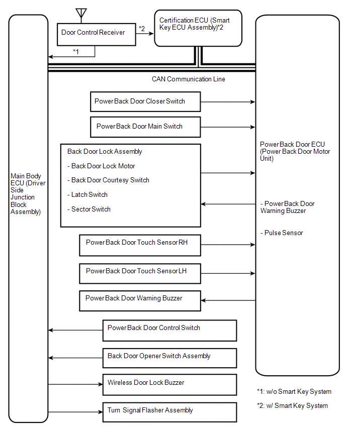 Communication Table
|
Sender |
Receiver |
Signal |
Line |
|---|---|---|---|
|
Main body ECU (Driver side junction block assembly) |
Power back door ECU (Power back door motor unit) |
|
CAN |
|
Power back door ECU (Power back door motor unit) |
Main body ECU (Driver side junction block assembly) |
|
CAN |
|
Certification ECU |
Main body ECU (Driver side junction block assembly) |
Transmitter switch signal |
CAN |
 System Description
SYSTEM DESCRIPTION
1. POWER BACK DOOR SYSTEM DESCRIPTION
(a) The power back door system controls the power back door by automatically
opening and closing the power back door with a motor.
(1) The ...
 How To Proceed With Troubleshooting
CAUTION / NOTICE / HINT
HINT:
Use the following procedures to troubleshoot the power back door system.
*: Use the Techstream.
PROCEDURE
1.
VEHICLE BROUG ...
Other materials about Toyota Venza:
System Diagram
SYSTEM DIAGRAM
Communication Method
Transmitting ECU
Receiver
Signal
Communication Method
Main body ECU (Driver Side Junction Block Assembly)
Power back door ECU (Power back door motor ...
Intermediate Shaft Speed Sensor "A" Circuit (P0791,P0793)
DESCRIPTION
This sensor detects the rotation speed of the counter gear which shows the output
speed of transaxle. By comparing the input turbine speed signal (NT) with the counter
gear speed sensor signal (NC), the TCM detects the shift timing of the gear ...
On-vehicle Inspection
ON-VEHICLE INSPECTION
PROCEDURE
1. INSPECT FOR COOLANT LEAK
HINT:
The sliding surface inside the engine water pump assembly is lubricated
by engine coolant. As some engine coolant is discharged during normal operation,
engine coolant residu ...

0.1144