Toyota Venza: Back Door Support
Components
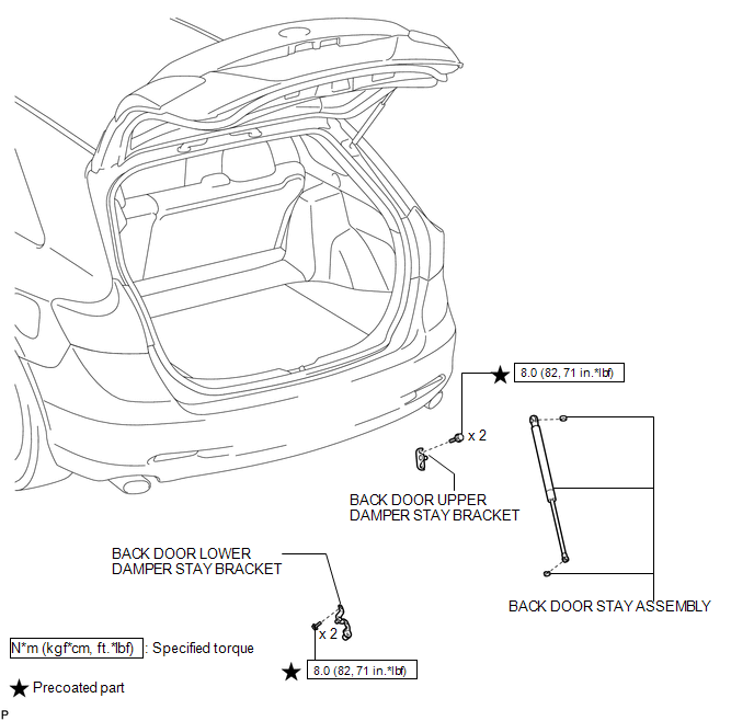
COMPONENTS
ILLUSTRATION
Removal
REMOVAL
PROCEDURE
1. REMOVE BACK DOOR STAY ASSEMBLY
NOTICE:
- Avoid touching the piston rod as much as possible to prevent foreign matter from attaching to it. Be sure to hold the cylinder while servicing.
- Do not wear cotton gloves or other similar materials when handling the piston rod. Fibers may attach to the rod and result in gas leaks.
- Do not apply any horizontal load to the door stay in order to prevent the piston rod from deforming.
|
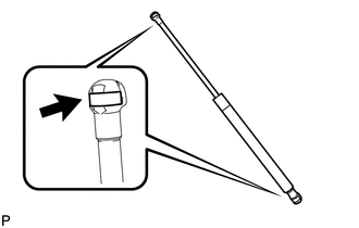
(a) Using a screwdriver, remove the stop ring along the groove. HINT: Tape the screwdriver tip before use. Text in Illustration
|
|
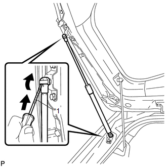
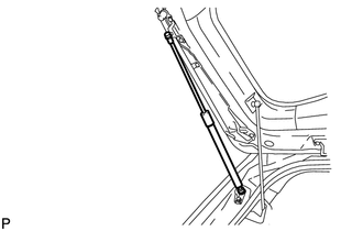
(b) Release the ball joint and remove the back door stay assembly.
NOTICE:
Remove the back door stay assembly while supporting the back door by hand.
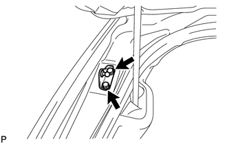
2. REMOVE BACK DOOR LOWER DAMPER STAY BRACKET
|
(a) Remove the 2 bolts and back door lower damper stay bracket. |
|
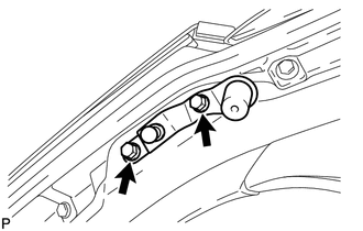
3. REMOVE BACK DOOR UPPER DAMPER STAY BRACKET
|
(a) Remove the 2 bolts and back door upper damper stay bracket. |
|
Disposal
DISPOSAL
PROCEDURE
1. DISPOSE OF BACK DOOR STAY ASSEMBLY
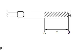
(a) Secure the back door stay assembly horizontally in a vise with the piston rod pulled out.
|
(b) Wear safety glasses. Use a metal saw to slowly cut a groove between A and B shown in the illustration to release the gas. Standard Dimension: a 80.0 mm (3.150 in.) NOTICE: Although the gas inside the back door stay assembly is colorless, odorless and harmless, metal debris may scatter. Therefore, cover the back door stay assembly with a piece of cloth or other material. |
|
Installation
INSTALLATION
PROCEDURE
1. INSTALL BACK DOOR UPPER DAMPER STAY BRACKET
(a) Clean the threaded portion on the vehicle body with a non-residue solvent.
(b) Apply adhesive to the threads of the 2 bolts.
Adhesive:
Toyota Genuine Adhesive 1324, Three Bond 1324 or equivalent
|
(c) Install the back door upper damper stay bracket with the 2 bolts. Torque: 8.0 N·m {82 kgf·cm, 71 in·lbf} |
|
.png)
2. INSTALL BACK DOOR LOWER DAMPER STAY BRACKET
(a) Clean the threaded portion on the vehicle body with a non-residue solvent.
(b) Apply adhesive to the threads of the 2 bolts.
Adhesive:
Toyota Genuine Adhesive 1324, Three Bond 1324 or equivalent
|
(c) Install the back door lower damper stay bracket with the 2 bolts. Torque: 8.0 N·m {82 kgf·cm, 71 in·lbf} |
|
.png)
3. INSTALL BACK DOOR STAY ASSEMBLY
NOTICE:
- Avoid touching the piston rod as much as possible to prevent foreign matter from attaching to it. Be sure to hold the cylinder while servicing.
- Do not wear cotton gloves or other similar materials when handling the piston rod. Fibers may attach to the rod and result in gas leaks.
- Do not apply any horizontal load to the door stay in order to prevent the rod from deforming.
(a) When reusing the back door stay assembly:
|
(1) Install the 2 stop rings to the back door stay assembly. |
|
|
(b) Install the back door stay assembly. NOTICE: Install the back door stay assembly while supporting the back door by hand. |
|
(c) Check that the back door stay assembly is engaged in the ball joint and that the back door stay assembly cannot be pulled out.
 Back Door Opener Switch
Components
COMPONENTS
ILLUSTRATION
Removal
REMOVAL
PROCEDURE
1. REMOVE BACK DOOR PANEL TRIM ASSEMBLY
2. REMOVE REAR LIGHT ASSEMBLY LH
3. REMOVE REAR LIGHT ASSEMBLY RH
HINT:
Use t ...
 Front Door
...
Other materials about Toyota Venza:
Steering wheel
The steering wheel can be adjusted to a comfortable position.
Hold the steering wheel and press the lever down.
Adjust to the ideal position by moving the steering wheel horizontally and vertically.
After adjustment, pull the lever up to secure the stee ...
Installation
INSTALLATION
PROCEDURE
1. INSTALL FRONT SHOULDER BELT ANCHOR ADJUSTER ASSEMBLY
(a) Engage the adjuster positioning hole with the guide and install the
front shoulder belt anchor adjuster assembly with the 2 bolts.
Torque:
42 N·m {428 ...
Control Module Communication Bus OFF (U0073/86,U0100/85,U0129/83)
DESCRIPTION
The AWD control ECU inputs the signals sent from the ECM and skid control
ECU via the CAN communication system.
When DTCs indicating a CAN communication system malfunction are output,
repair the CAN communication system before r ...

0.1271