Toyota Venza: Wireless Door Lock Buzzer
Components
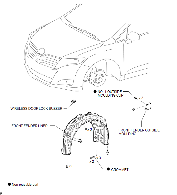
COMPONENTS
ILLUSTRATION
Installation
INSTALLATION
PROCEDURE
1. INSTALL WIRELESS DOOR LOCK BUZZER
|
(a) Engage the clamp and install the wireless door lock buzzer. |
|
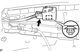
(b) Connect the connector.
2. INSTALL FRONT FENDER LINER
.gif)
3. INSTALL FRONT FENDER OUTSIDE MOULDING
4. INSTALL FRONT WHEEL
Removal
REMOVAL
PROCEDURE
1. REMOVE FRONT WHEEL
2. REMOVE FRONT FENDER OUTSIDE MOULDING
.gif)
3. REMOVE FRONT FENDER LINER
4. REMOVE WIRELESS DOOR LOCK BUZZER
|
(a) Disconnect the connector. |
|
.png)
(b) Disengage the clamp and remove the wireless door lock buzzer.
 Installation
INSTALLATION
PROCEDURE
1. INSTALL UNLOCK WARNING SWITCH
(a) Engage the 2 claws and install the unlock warning switch to the steering
column upper bracket.
...

Other materials about Toyota Venza:
Diagnostic Trouble Code Chart
DIAGNOSTIC TROUBLE CODE CHART
If a trouble code is displayed during the DTC check, check the parts listed for
that code in the table below and proceed to the appropriate page.
HINT:
The steering lock ECU does not store DTCs regarding the past problems.
S ...
Lost Communication with "Door Control Module B" (U0200)
DESCRIPTION
DTC No.
DTC Detection Condition
Trouble Area
U0200
No communication from the outer mirror control ECU assembly (for driver
side).
Outer mirror control ECU assem ...
On-vehicle Inspection
ON-VEHICLE INSPECTION
PROCEDURE
1. CHECK STEERING EFFORT (TORQUE)
NOTICE:
Some of these service operations may affect the SRS airbags. Read the precautionary
notices concerning the SRS airbag system before servicing.
(a) Stop the vehicle on a level, pav ...

0.1466