
Toyota Venza: USB Audio System Recognition/Play Error
DESCRIPTION
When a USB device or "iPod" is connected to the USB jack of the No. 1 stereo jack adapter assembly, it must have playable files. The device must also communicate with and be recognized by the radio and display receiver assembly. This diagnostic procedure is for when a device is not recognized, or files from the device cannot be played normally.
WIRING DIAGRAM
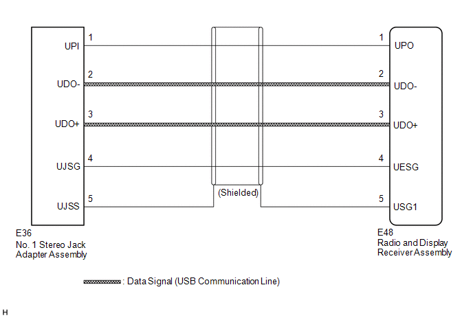
CAUTION / NOTICE / HINT
HINT:
- When a large amount of data is in a USB device, it may take a while to begin playback.
- When using a USB device, files that are protected by copyright cannot be played.
- When files are not played in the sorted order, perform the following
procedure before inspection.
- Add numbers in front of the file names.
- Put the files in a folder and copy the folder data to the USB device.
PROCEDURE
|
1. |
CHECK USB DEVICE OR "iPod" |
(a) Disconnect the USB device or "iPod" from the No. 1 stereo jack adapter assembly.
(b) Check if playable files are present on the USB device or "iPod".
HINT:
Refer to System Description for playable files (See page
.gif) ).
).
(c) Check if the USB device is a compatible format or "iPod" is a compatible version.
HINT:
Refer to System Description for compatible formats and versions (See page
).
|
Result |
Proceed to |
|---|---|
|
No playable files exist, or incompatible device format or version. |
A |
|
Playable files exist, and compatible device format or version. |
B |
| A | .gif) |
END (USB DEVICE FORMAT WAS INCOMPATIBLE, "iPod" VERSION WAS INCOMPATIBLE, OR NO PLAYABLE FILES EXIST) |
|
.gif)
|
2. |
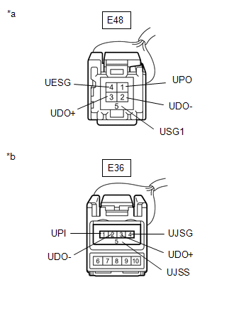
CHECK HARNESS AND CONNECTOR (RADIO AND DISPLAY RECEIVER ASSEMBLY - NO. 1 STEREO JACK ADAPTER ASSEMBLY) |
(a) Disconnect the E48 radio and display receiver assembly connector.
(b) Disconnect the E36 No. 1 stereo jack adapter assembly connector.
|
(c) Measure the resistance according to the value(s) in the table below. Standard Resistance:
|
|
| NG | |
REPAIR OR REPLACE HARNESS OR CONNECTOR |
|
|
3. |
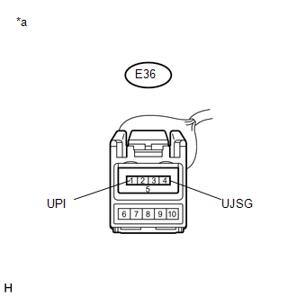
INSPECT RADIO AND DISPLAY RECEIVER ASSEMBLY (NO. 1 STEREO JACK ADAPTER ASSEMBLY POWER SOURCE) |
(a) Disconnect E36 No. 1 stereo jack adapter assembly connector.
|
(b) Measure the voltage according to the value(s) in the table below. Standard Voltage:
|
|
| NG | |
REPLACE RADIO AND DISPLAY RECEIVER ASSEMBLY |
|
|
4. |
FORMAT USB DEVICE OR RESTORE "iPod" AND RECHECK |
(a) Delete all files in the USB device or "iPod" and format/restore it.
(b) Save the data again and check if it can be played on the in-vehicle device.
NOTICE:
Formatting a USB device or restoring an "iPod" erases all music on the device. Ensure that a backup of the music data is available before performing this operation.
OK:
Malfunction disappears.
| OK | |
END |
|
|
5. |
REPLACE USB DEVICE OR "iPod" |
(a) Turn the ignition switch off.
HINT:
When this malfunction occurs, it is necessary to turn the ignition switch off to make it possible for the vehicle to recognize a new device when it is connected.
(b) Turn the ignition switch to ACC.
(c) Connect a known good USB device or "iPod" to the No. 1 stereo jack adapter assembly.
HINT:
- If the malfunction occurred when a USB device was in use, use another USB device for the inspection. If the malfunction occurred when an "iPod" was in use, use another "iPod" for the inspection.
- Refer to System Description for compatible formats and versions (See
page ).
|
|
6. |
CHECK USB DEVICE OR "iPod" |
(a) Check if a USB device or "iPod" is recognized by the radio and display receiver assembly, and if information such as track, artist and album names is displayed on the screen.
OK:
USB device or "iPod" is recognized properly and the information is displayed on the screen.
| OK | |
USB DEVICE OR "iPod" WAS INCOMPATIBLE OR DEFECTIVE |
| NG | |
PROCEED TO NEXT SUSPECTED AREA SHOWN IN PROBLEM SYMPTOMS TABLE |
 Black Screen
PROCEDURE
1.
CHECK DISPLAY SETTING
(a) Check that the display is not in screen off mode.
OK:
The display setting is not in screen off mode.
NG
...
 Vehicle Speed Signal Circuit between Radio Receiver and Combination Meter
DESCRIPTION
for Automatic Sound Levelizer (ASL):
This circuit is necessary for the Automatic Sound Levelizer (ASL) built
into the radio and display receiver assembly.
The Automatic So ...
Other materials about Toyota Venza:
Lost Communication with TCM (U0101)
DESCRIPTION
The Transmission Control Module (TCM) and ECM perform 2-way communication with
each other via the Controller Area Network (CAN). The TCM sends signals to the ECM
concerning required engine speed, required engine torque, warning indicators in
...
Removal
REMOVAL
PROCEDURE
1. REMOVE UPPER CONSOLE PANEL SUB-ASSEMBLY (w/o Seat Heater System)
2. REMOVE UPPER CONSOLE PANEL SUB-ASSEMBLY (w/ Seat Heater System)
3. REMOVE NO. 2 CONSOLE BOX CARPET
4. REMOVE CONSOLE BOX ASSEMBLY
5. REMOVE AIR CONDITION ...
Evaporative Emission Control System Leak Detected (Gross Leak) (P0455,P0456)
DTC SUMMARY
DTC No.
Monitoring Item
Malfunction Detection Condition
Trouble Area
Detection Timing
Detection Logic
P0455
EVAP gross leak
Leak detection pum ...

0.15