Toyota Venza: Short to GND in Immobiliser System Power Source Circuit (B278A)
DESCRIPTION
This DTC is stored when the engine switch power source supply line is open or shorted.
|
DTC No. |
DTC Detection Condition |
Trouble Area |
|---|---|---|
|
B278A |
Engine switch power source supply line is open or shorted. |
|
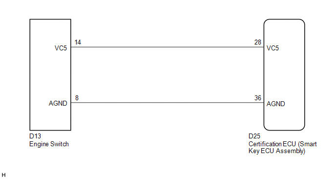
WIRING DIAGRAM
CAUTION / NOTICE / HINT
NOTICE:
If the certification ECU (smart key ECU assembly) is replaced, register the key
(See page .gif) ).
).
PROCEDURE
|
1. |
CHECK DTC OUTPUT |
(a) Clear the DTCs (See page ).
(b) Recheck for DTCs (See page ).
OK:
DTC B278A is not output.
| OK | .gif) |
USE SIMULATION METHOD TO CHECK |
|
.gif)
|
2. |
CHECK HARNESS AND CONNECTOR (CERTIFICATION ECU - ENGINE SWITCH) |
(a) Disconnect the certification ECU (smart key ECU assembly) connector.
|
(b) Disconnect the engine switch connector. |
|
(c) Measure the resistance according to the value(s) in the table below.
Standard Resistance:
|
Tester Connection |
Condition |
Specified Condition |
|---|---|---|
|
D25-28 (VC5) - D13-14 (VC5) |
Always |
Below 1 Ω |
|
D25-36 (AGND) - D13-8 (AGND) |
Always |
Below 1 Ω |
|
D25-28 (VC5) - Body ground |
Always |
10 kΩ or higher |
|
D25-36 (AGND) - Body ground |
Always |
10 kΩ or higher |
|
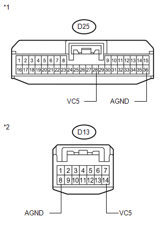
*1 |
Front view of wire harness connector (to Certification ECU (Smart Key ECU Assembly)) |
|
*2 |
Front view of wire harness connector (to Engine Switch) |
| NG | |
REPAIR OR REPLACE HARNESS OR CONNECTOR |
|
|
3. |
CHECK CERTIFICATION ECU (SMART KEY ECU ASSEMBLY) |
(a) Reconnect the certification ECU (smart key ECU assembly) connector.
(b) Reconnect the engine switch connector.
(c) Using an oscilloscope, check the waveform.
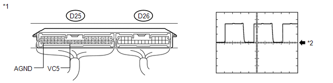
Waveform (Reference):
|
Item |
Content |
|---|---|
|
Tester Connection |
D25-28 (VC5) - D25-36 (AGND) |
|
Tool Setting |
2 V/DIV., 200 ms./DIV. |
|
Condition |
|
OK:
Waveform is output normally (see illustration)
|
Result |
Proceed to |
|---|---|
|
NG |
A |
|
OK (for 2GR-FE) |
B |
|
OK (for 1AR-FE) |
C |
|
*1 |
Component with harness connected (Certification ECU (Smart Key ECU Assembly)) |
|
*2 |
GND |
| A | |
REPLACE CERTIFICATION ECU (SMART KEY ECU ASSEMBLY) |
| B | |
REPLACE ENGINE SWITCH |
| C | |
REPLACE ENGINE SWITCH |
 Theft Deterrent System Communication Line High Fixation (B279A)
DESCRIPTION
If the communication line (EFIO - IMI) to the certification ECU (smart key ECU
assembly) is stuck high output (e.g. shorted to +B), the ECM stores this DTC.
DTC No.
...
 Engine Immobiliser System Malfunction (B2799)
DESCRIPTION
This DTC is stored when one of the following occurs: 1) the ECM detects an error
in its own communication with the certification ECU (smart key ECU assembly); 2)
the ECM detects an er ...
Other materials about Toyota Venza:
Inspection
INSPECTION
PROCEDURE
1. INSPECT SHIFT LOCK CONTROL UNIT ASSEMBLY (w/o Smart Key System)
(a) Measure the voltage according to the value(s) in the table below.
Text in Illustration
*1
Component with harness c ...
SRS Warning Light does not Come ON
DESCRIPTION
The SRS warning light is located on the combination meter assembly.
When the SRS is normal, the SRS warning light comes on for approximately 6 seconds
after the ignition switch is turned from off to ON, and then goes off automatically.
If ther ...
Driver Side Power Mirror cannot be Adjusted with Power Mirror Switch
SYSTEM DESCRIPTION
When the mirror adjust switch is operated, the main body ECU (driver side junction
block assembly) detects the switch operation and sends the mirror adjust switch
signal to the outer mirror control ECU assembly (driver door) via CAN com ...

0.1603