Toyota Venza: Terminals Of Ecu
TERMINALS OF ECU
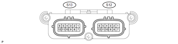
1. OCCUPANT CLASSIFICATION ECU (for Power Seat)
|
Terminal No. (Symbol) |
Wiring Color |
Terminal Description |
Condition |
Specification |
|---|---|---|---|---|
|
S12-1 (+B) - S12-3 (GND) |
GR - W-B |
Battery |
Always |
10 to 14 V |
|
S12-2 (DIA) - S12-3 (GND) |
SB - W-B |
Diagnosis (DLC3) |
Ignition switch ON |
Pulse generation |
|
S12-3 (GND) - Body ground |
W-B - Body ground |
Ground |
Always |
Below 1 V |
|
S12-4 (FSR-) - S12-3 (GND) |
B - W-B |
Center airbag sensor assembly communication line (-) |
Always |
Below 1 V |
|
S12-5 (BGND) - S12-3 (GND) |
GR - W-B |
Passenger side buckle switch ground line |
Always |
Below 1 V |
|
S12-7 (IG) - S12-3 (GND) |
V - W-B |
Power source (ECU-B fuse) |
Ignition switch ON |
10 to 14 V |
|
S12-8 (FSR+) - S12-4 (FSR-) |
W - B |
Center airbag sensor assembly communication line |
Ignition switch ON |
Pulse generation |
|
S12-9 (BSW) - S12-5 (BGND) |
L - GR |
Passenger side buckle switch line |
Always |
4 to 14 V |
|
S13-1 (SGD1) - S12-3 (GND) |
R - W-B |
Front occupant classification sensor LH ground line |
Always |
Below 1 V |
|
S13-2 (SGD2) - S12-3 (GND) |
Y - W-B |
Front occupant classification sensor RH ground line |
Always |
Below 1 V |
|
S13-3 (SGD3) - S12-3 (GND) |
BR - W-B |
Rear occupant classification sensor LH ground line |
Always |
Below 1 V |
|
S13-4 (SGD4) - S12-3 (GND) |
LG - W-B |
Rear occupant classification sensor RH ground line |
Always |
Below 1 V |
|
S13-5 (SVC3) - S13-3 (SGD3) |
G - BR |
Rear occupant classification sensor LH power supply line |
Ignition switch ON, a load applied to rear occupant classification sensor LH |
4.9 to 5.1 V |
|
S13-6 (SVC4) - S13-4 (SGD4) |
GR - LG |
Rear occupant classification sensor RH power supply line |
Ignition switch ON, a load applied to rear occupant classification sensor RH |
4.9 to 5.1 V |
|
S13-7 (SIG1) - S13-1 (SGD1) |
P - R |
Front occupant classification sensor LH signal line |
Ignition switch ON, a load applied to front occupant classification sensor LH |
0 to 5.1 V |
|
S13-8 (SIG2) - S13-2 (SGD2) |
GR - Y |
Front occupant classification sensor RH signal line |
Ignition switch ON, a load applied to front occupant classification sensor RH |
0 to 5.1 V |
|
S13-9 (SIG3) - S13-3 (SGD3) |
L - BR |
Rear occupant classification sensor LH signal line |
Ignition switch ON, a load applied to rear occupant classification sensor LH |
0 to 5.1 V |
|
S13-10 (SIG4) - S13-4 (SGD4) |
SB - LG |
Rear occupant classification sensor RH signal line |
Ignition switch ON, a load applied to rear occupant classification sensor RH |
0 to 5.1 V |
|
S13-11 (SVC1) - S13-1 (SGD1) |
Y - R |
Front occupant classification sensor LH power supply line |
Ignition switch ON, a load applied to front occupant classification sensor LH |
4.9 to 5.1 V |
|
S13-12 (SVC2) - S13-2 (SGD2) |
V - Y |
Front occupant classification sensor RH power supply line |
Ignition switch ON, a load applied to front occupant classification sensor RH |
4.9 to 5.1 V |
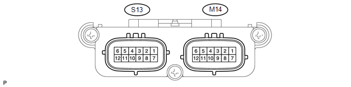
2. OCCUPANT CLASSIFICATION ECU (for Manual Seat)
|
Terminal No. (Symbol) |
Wiring Color |
Terminal Description |
Condition |
Specification |
|---|---|---|---|---|
|
M14-1 (+B) - M14-3 (GND) |
G - W-B |
Battery |
Always |
10 to 14 V |
|
M14-2 (DIA) - M14-3 (GND) |
SB - W-B |
Diagnosis (DLC3) |
Ignition switch ON |
Pulse generation |
|
M14-3 (GND) - Body ground |
W-B - Body ground |
Ground |
Always |
Below 1 V |
|
M14-4 (FSR-) - M14-3 (GND) |
B - W-B |
Center airbag sensor assembly communication line (-) |
Always |
Below 1 V |
|
M14-5 (BGND) - M14-3 (GND) |
Y - W-B |
Passenger side buckle switch ground line |
Always |
Below 1 V |
|
M14-7 (IG) - M14-3 (GND) |
V - W-B |
Power source (ECU-B fuse) |
Ignition switch ON |
10 to 14 V |
|
M14-8 (FSR+) - M14-4 (FSR-) |
W - B |
Center airbag sensor assembly communication line |
Ignition switch ON |
Pulse generation |
|
M14-9 (BSW) - M14-5 (BGND) |
G - Y |
Passenger side buckle switch line |
Always |
4 to 14 V |
|
S13-1 (SGD1) - M14-3 (GND) |
Y - W-B |
Front occupant classification sensor LH ground line |
Always |
Below 1 V |
|
S13-2 (SGD2) - M14-3 (GND) |
SB - W-B |
Front occupant classification sensor RH ground line |
Always |
Below 1 V |
|
S13-3 (SGD3) - M14-3 (GND) |
L - W-B |
Rear occupant classification sensor LH ground line |
Always |
Below 1 V |
|
S13-4 (SGD4) - M14-3 (GND) |
W - W-B |
Rear occupant classification sensor RH ground line |
Always |
Below 1 V |
|
S13-5 (SVC3) - S13-3 (SGD3) |
R - L |
Rear occupant classification sensor LH power supply line |
Ignition switch ON, a load applied to rear occupant classification sensor LH |
4.9 to 5.1 V |
|
S13-6 (SVC4) - S13-4 (SGD4) |
B - W |
Rear occupant classification sensor RH power supply line |
Ignition switch ON, a load applied to rear occupant classification sensor RH |
4.9 to 5.1 V |
|
S13-7 (SIG1) - S13-1 (SGD1) |
BE - Y |
Front occupant classification sensor LH signal line |
Ignition switch ON, a load applied to front occupant classification sensor LH |
0 to 5.1 V |
|
S13-8 (SIG2) - S13-2 (SGD2) |
GR - SB |
Front occupant classification sensor RH signal line |
Ignition switch ON, a load applied to front occupant classification sensor RH |
0 to 5.1 V |
|
S13-9 (SIG3) - S13-3 (SGD3) |
G - L |
Rear occupant classification sensor LH signal line |
Ignition switch ON, a load applied to rear occupant classification sensor LH |
0 to 5.1 V |
|
S13-10 (SIG4) - S13-4 (SGD4) |
V - W |
Rear occupant classification sensor RH signal line |
Ignition switch ON, a load applied to rear occupant classification sensor RH |
0 to 5.1 V |
|
S13-11 (SVC1) - S13-1 (SGD1) |
P - Y |
Front occupant classification sensor LH power supply line |
Ignition switch ON, a load applied to front occupant classification sensor LH |
4.9 to 5.1 V |
|
S13-12 (SVC2) - S13-2 (SGD2) |
BR - SB |
Front occupant classification sensor RH power supply line |
Ignition switch ON, a load applied to front occupant classification sensor RH |
4.9 to 5.1 V |
 Problem Symptoms Table
PROBLEM SYMPTOMS TABLE
HINT:
Use the table below to help determine the cause of problem symptoms.
If multiple suspected areas are listed, the potential causes of the symptoms
are lis ...
 Diagnosis System
DIAGNOSIS SYSTEM
1. CHECK DLC3
(a) Check the DLC3 (See page ).
2. FUNCTION OF PASSENGER AIRBAG ON/OFF INDICATOR
(a) Initial check.
(1) Turn the ignition switch to ON.
(2) The passenger airbag O ...
Other materials about Toyota Venza:
Removal
REMOVAL
CAUTION / NOTICE / HINT
NOTICE:
Do not remove the oil pump or oil pump relief valve from the timing chain cover
sub-assembly.
PROCEDURE
1. INSTALL ENGINE ON ENGINE STAND
(See page )
2. REMOVE IGNITION COIL ASSEMBLY
3. REMOVE CYLINDER HEAD ...
Terminals Of Ecu
TERMINALS OF ECU
1. TCM
HINT:
Each TCM terminal standard voltage is shown in the table below.
In the table, first follow the information under "Condition". Look under "Terminal
No. (Symbol)" for the terminals to be inspected. The st ...
On-vehicle Inspection
ON-VEHICLE INSPECTION
PROCEDURE
1. INSPECT REAR COMBINATION LIGHT ASSEMBLY
(a) Disconnect the connector from the rear combination light assembly.
(b) Measure the voltage according to the value(s) in ...

0.1693