Toyota Venza: Terminals Of Ecu
TERMINALS OF ECU
1. CHECK POSITION CONTROL ECU AND SWITCH ASSEMBLY
(a) Disconnect the T10 and T11 position control ECU and switch assembly connectors.

(b) Measure the voltage and resistance according to the value(s) in the table below.
HINT:
Measure the values on the wire harness side with the connector disconnected.
|
Tester Connection |
Wiring Color |
Terminal Description |
Condition |
Specified Condition |
|---|---|---|---|---|
|
T10-1 (GND) - Body ground |
W - Body ground |
Ground |
Always |
Below 1 Ω |
|
T11-4 (DBCL) - T10-1 (GND) |
L - W |
Driver seat belt buckle switch signal |
Driver seat belt fastened |
Below 1 Ω |
|
T11-4 (DBCL) - T10-1 (GND) |
L - W |
Driver seat belt buckle switch signal |
Driver seat belt unfastened |
10 kΩ or higher |
|
T10-6 (+B) - T10-1 (GND) |
L - W |
Power source |
Always |
11 to 14 V |
|
T11-12 (SYSB) - T10-1 (GND) |
W - W |
System power source |
Always |
11 to 14 V |
If the result is not as specified, there may be a malfunction on the wire harness side.
(c) Reconnect the T10 and T11 position control ECU and switch assembly connectors.
(d) Measure the voltage and according to the value(s) in the table below.
|
Tester Connection |
Wiring Color |
Terminal Description |
Condition |
Specified Condition |
|---|---|---|---|---|
|
T10-2 (SLD+) - T10-1 (GND) |
Y - W |
Sliding motor signal (forward) |
Slide switch off |
Below 1 V |
|
Slide switch on (Forward) |
11 to 14 V |
|||
|
T10-4 (SLD-) - T10-1 (GND) |
G - W |
Sliding motor signal (rearward) |
Slide switch off |
Below 1 V |
|
Slide switch on (Rearward) |
11 to 14 V |
|||
|
T10-7 (FRV+) - T10-1 (GND) |
GR - W |
Front vertical motor signal (upward) |
Front vertical switch off |
Below 1 V |
|
Front vertical switch on (Upward) |
11 to 14 V |
|||
|
T10-5 (FRV-) - T10-1 (GND) |
LG - W |
Front vertical motor signal (downward) |
Front vertical switch off |
Below 1 V |
|
Front vertical switch on (Downward) |
11 to 14 V |
|||
|
T10-8 (LFT+) - T10-1 (GND) |
SB - W |
Lifter motor signal (upward) |
Lifter switch off |
Below 1 V |
|
Lifter switch on (Upward) |
11 to 14 V |
|||
|
T10-11 (LFT-) - T10-1 (GND) |
P - W |
Lifter motor signal (downward) |
Lifter switch off |
Below 1 V |
|
Lifter switch on (Downward) |
11 to 14 V |
|||
|
T10-9 (RCL+) - T10-1 (GND) |
L - W |
Reclining motor signal (forward) |
Reclining switch off |
Below 1 V |
|
Reclining switch on (Forward) |
11 to 14 V |
|||
|
T10-12 (RCL-) - T10-1 (GND) |
R - W |
Reclining motor signal (rearward) |
Reclining switch off |
Below 1 V |
|
Reclining switch on (Rearward) |
11 to 14 V |
If the result is not as specified, the position control ECU and switch assembly may have a malfunction.
2. CHECK OUTER MIRROR CONTROL ECU ASSEMBLY LH
(a) Disconnect the I13 outer mirror control ECU assembly LH connector.

(b) Measure the voltage and resistance according to the value(s) in the table below.
HINT:
Measure the values on the wire harness side with the connector disconnected.
|
Tester Connection |
Wiring Color |
Terminal Description |
Condition |
Specified Condition |
|---|---|---|---|---|
|
I13-7 (GND) - Body ground |
W-B - Body ground |
Ground |
Always |
Below 1 Ω |
|
I13-14 (BDR) - I13-7 (GND) |
V - W-B |
Power source |
Always |
11 to 14 V |
|
I13-5 (SIG) - I13-7 (GND) |
L - W-B |
Power source (IG) |
Ignition switch off |
Below 1 V |
|
Ignition switch ON |
11 to 14 V |
|||
|
I13-6 (CPUB) - I13-7 (GND) |
LG - W-B |
Power source |
Always |
11 to 14 V |
If the result is not as specified, there may be a malfunction in the wire harness.
(c) Reconnect the I13 outer mirror control ECU assembly LH connector.
(d) Measure the voltage according to the value(s) in the table below.
|
Tester Connection |
Wiring Color |
Terminal Description |
Condition |
Specified Condition |
|---|---|---|---|---|
|
I13-3 (M2) - I13-13 (MSWE) |
V - Y |
M2 switch signal for seat memory switch |
M2 switch on |
Below 1 V |
|
M2 switch off |
11 to 14 V |
|||
|
I13-2 (M1) - I13-13 (MSWE) |
B - Y |
M1 switch signal for seat memory switch |
M1 switch on |
Below 1 V |
|
M1 switch off |
11 to 14 V |
|||
|
I13-1 (MM) - I13-13 (MSWE) |
GR - Y |
SET switch signal for seat memory switch |
SET switch on |
Below 1 V |
|
SET switch off |
11 to 14 V |
If the result is not as specified, the outer mirror control ECU assembly LH may have a malfunction.
3. CHECK MAIN BODY ECU (DRIVER SIDE JUNCTION BLOCK ASSEMBLY)
(a) Disconnect the main body ECU (driver side junction block assembly) connectors.
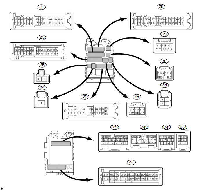
(b) Measure the resistance and voltage according to the value(s) in the table below.
HINT:
Measure values on the wire harness side with the connectors disconnected.
|
Tester Connection |
Wiring Color |
Terminal Description |
Condition |
Specified Condition |
|---|---|---|---|---|
|
D50-24 (DCTY) - Body ground |
V - Body ground |
Driver side door courtesy light switch input |
Driver side door closed (OFF) → open (ON) |
10 kΩ or higher → Below 1 Ω |
|
2A-1 (ACC) - Body ground |
B - Body ground |
Ignition power supply (ACC signal) |
Ignition switch ACC → OFF |
11 to 14 V → Below 1 V |
|
2A-1 (IG) - Body ground |
B - Body ground |
Ignition power supply (IG signal) |
Ignition switch ON → OFF |
11 to 14 V → Below 1 V |
|
2C-30 (ALTB) - Body ground |
BR - Body ground |
+B (power system alternator system) power supply |
Always |
11 to 14 V |
|
2F-16 (GND1) - Body ground |
W-B - Body ground |
Ground |
Always |
Below 1 Ω |
|
2C-24 (BECU) - Body ground |
L - Body ground |
+B power supply |
Always |
11 to 14 V |
If the result is not as specified, there may be a malfunction in the wire harness.
 Diagnosis System
DIAGNOSIS SYSTEM
1. DESCRIPTION
(a) Front power seat control system (w/ Memory) data and Diagnostic Trouble Codes
(DTCs) can be read through the Data Link Connector 3 (DLC3) of the vehicle. When
...
 Dtc Check / Clear
DTC CHECK / CLEAR
1. CHECK DTC
(a) Connect the Techstream to the DLC3.
(b) Turn the ignition switch to ON.
(c) Turn the Techstream on.
(d) Enter the following menus: Body Electrical / Driver Seat ...
Other materials about Toyota Venza:
LVDS Signal Malfunction (from Extension Module) (B1532)
DESCRIPTION
The stereo component tuner assembly and the radio and display receiver assembly
are connected by an LVDS communication line.
This DTC is stored when an LVDS communication error occurs between the stereo
component tuner assembly and the radio ...
Dinghy towing
Your vehicle is not designed to be dinghy towed (with four wheels on the ground)
behind a motor home.
NOTICE
- To avoid serious damage to your vehicle
Do not tow your vehicle with four wheels on the ground.
- To prevent causing serious dama ...
Removal
REMOVAL
PROCEDURE
1. REMOVE REAR SEAT HEADREST ASSEMBLY
2. REMOVE REAR SEAT CENTER HEADREST ASSEMBLY
3. REMOVE REAR SEAT INNER TRACK BRACKET COVER
4. REMOVE REAR SEAT OUTER TRACK BRACKET COVER
5. DISCONNECT REAR SEAT RECLINING CONTROL CABLE S ...

0.1338