Toyota Venza: Tire Pressure Warning Receiver
Components
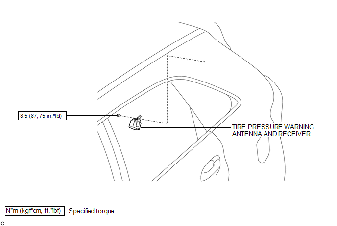
COMPONENTS
ILLUSTRATION
Removal
REMOVAL
PROCEDURE
1. DISCONNECT CABLE FROM NEGATIVE BATTERY TERMINAL
NOTICE:
When disconnecting the cable, some systems need to be initialized after the cable
is reconnected (See page .gif) ).
).
2. REMOVE ROOF SIDE INNER GARNISH ASSEMBLY LH
HINT:
- Refer to the procedures up to "Remove roof side inner garnish assembly"
(See page ).
- Removal should be performed only for the left side.
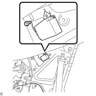
3. REMOVE TIRE PRESSURE WARNING ANTENNA AND RECEIVER
|
(a) Remove the bolt. |
|
|
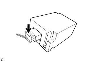
(b) Disconnect the connector to remove the tire pressure warning antenna and receiver. |
|
Installation
INSTALLATION
PROCEDURE
1. INSTALL TIRE PRESSURE WARNING ANTENNA AND RECEIVER
|
(a) Connect the connector. |
|
.png)
|
(b) Engage the 2 tabs into the holes as shown in the illustration to install the tire pressure warning antenna and receiver. |
|
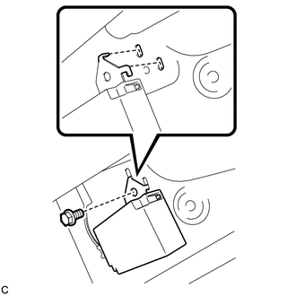
(c) Install the bolt.
Torque:
8.5 N·m {87 kgf·cm, 75 in·lbf}
2. INSTALL ROOF SIDE INNER GARNISH ASSEMBLY LH
HINT:
- Refer to the procedures from "Install roof side inner garnish assembly"
(See page
.gif) ).
). - Installation should be performed only for the left side.
3. CONNECT CABLE TO NEGATIVE BATTERY TERMINAL
NOTICE:
When disconnecting the cable, some systems need to be initialized after the cable
is reconnected (See page ).
4. INSPECT TIRE PRESSURE WARNING SYSTEM
(a) Inspect the tire pressure warning system (See page
).
 Tire Pressure Warning Ecu
Components
COMPONENTS
ILLUSTRATION
ILLUSTRATION
Removal
REMOVAL
CAUTION / NOTICE / HINT
NOTICE:
Before removing the tire pressure warning ECU, read the registered transmitter
IDs of ...

Other materials about Toyota Venza:
Inspection
INSPECTION
PROCEDURE
1. INSPECT TIE ROD ASSEMBLY LH
(a) Secure the tie rod assembly LH in a vise.
(b) Install the nut to the stud bolt.
(c) Flip the ball joint back and forth 5 times.
(d) Set a to ...
Fail-safe Chart
FAIL-SAFE CHART
If any of the following DTCs are stored, the ECM enters fail-safe mode to allow
the vehicle to be driven temporarily or stops fuel injection.
DTC Code
Component
Fail-Safe Operation
Fail-Safe Deact ...
Diagnostic Trouble Code Chart
DIAGNOSTIC TROUBLE CODE CHART
HINT:
If a trouble code is stored during the DTC check, inspect the trouble areas listed
for that code. For details of the code, refer to the "See page" below.
1. CERTIFICATION ECU (SMART KEY ECU ASSEMBLY) DIAGNOSTI ...

0.1673