Toyota Venza: System Diagram
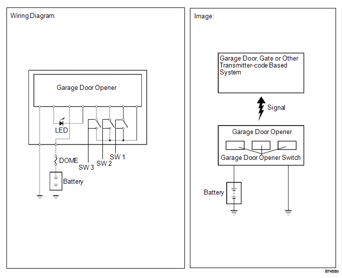
SYSTEM DIAGRAM
 Parts Location
PARTS LOCATION
ILLUSTRATION
...
 Registration
REGISTRATION
PROCEDURE
1. REGISTER TRANSMITTER CODE
HINT:
The vehicles garage door opener system records transmitter codes for
systems such as garage doors, gates, door locks, home lig ...
Other materials about Toyota Venza:
Cleaning and protecting the vehicle interior
The following procedures will help protect your vehicle’s interior and keep
it in top condition: - Protecting the vehicle interior
Remove dirt and dust using a vacuum cleaner. Wipe dirty surfaces with a cloth dampened
with lukewarm water.
- Cleaning t ...
Installation
INSTALLATION
PROCEDURE
1. INSTALL POWER SEAT SWITCH
(a) Install the power seat switch with the 3 screws.
(b) Connect the connector.
2. INSTALL FRONT SEAT CUSHION SHIELD ASSEMBLY
3. INSTALL SLID ...
System Description
SYSTEM DESCRIPTION
1. WIRELESS DOOR LOCK CONTROL SYSTEM
The wireless door lock control system can be used to lock and unlock all doors
from a distance. The system is controlled by a door control transmitter which sends
radio waves to the door control rec ...

0.1533