Toyota Venza: System Diagram
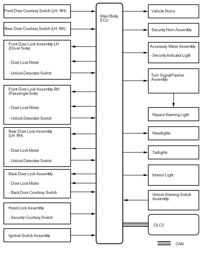
SYSTEM DIAGRAM
 System Description
SYSTEM DESCRIPTION
1. OUTLINE OF THEFT DETERRENT SYSTEM
The theft deterrent system can be set by locking the doors using the
transmitter or key, or by opening and closing the doors (for d ...
 How To Proceed With Troubleshooting
CAUTION / NOTICE / HINT
HINT:
Use this procedure to troubleshoot the theft deterrent system.
*: Use the Techstream.
PROCEDURE
1.
VEHICLE BROUGHT TO WORKSHO ...
Other materials about Toyota Venza:
Monitor Drive Pattern
MONITOR DRIVE PATTERN
1. TEST MONITOR DRIVE PATTERN FOR ECT
CAUTION:
Perform this drive pattern on a level surface and strictly observe the posted
speed limits and traffic laws while driving.
HINT:
Performing this drive pattern is one method to simulate ...
Brake Switch "A" Circuit (P0571)
DESCRIPTION
When the brake pedal is depressed, the stop light switch assembly sends a signal
to the ECM. When the ECM receives this signal, it cancels the cruise control. The
fail-safe function operates to enable normal driving even if there is a malfunct ...
System Description
SYSTEM DESCRIPTION
1. POWER MIRROR CONTROL SYSTEM DESCRIPTION
(a) This system has the following functions: power retract mirror function*,
reverse shift-linked function, electrical remote control function, memory function
and mirror heater function.
...

0.213