Toyota Venza: No Response from Steering Lock ECU (B2786)
DESCRIPTION
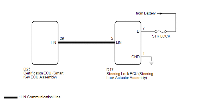
This DTC is stored when LIN communication between the certification ECU (smart key ECU assembly) and steering lock ECU (steering lock actuator assembly) stops for more than 10 seconds.
|
DTC No. |
DTC Detection Condition |
Trouble Area |
|---|---|---|
|
B2786 |
No communication between the steering lock ECU (steering lock actuator assembly) and certification ECU (smart key ECU assembly) for more than 10 seconds. |
|
WIRING DIAGRAM
CAUTION / NOTICE / HINT
NOTICE:
- If the certification ECU (smart key ECU assembly) is replaced, register the key.
- If the steering lock ECU (steering lock actuator assembly) is replaced, register the ECU code.
- When using the Techstream to troubleshoot with the ignition switch off:
Connect the Techstream to the DLC3, and turn the courtesy switch on and off at 1.5-second intervals until communication between the Techstream and vehicle begins.
PROCEDURE
|
1. |
CHECK HARNESS AND CONNECTOR (STEERING LOCK ECU - BATTERY AND BODY GROUND) |
|
(a) Disconnect the D17 ECU connector. |
|
(b) Measure the resistance and voltage according to the value(s) in the table below.
Standard Resistance:
|
Tester Connection |
Condition |
Specified Condition |
|---|---|---|
|
D17-1 (GND) - Body ground |
Always |
Below 1 Ω |
Standard Voltage:
|
Tester Connection |
Condition |
Specified Condition |
|---|---|---|
|
D17-7 (B) - Body ground |
Always |
11 to 14 V |
|
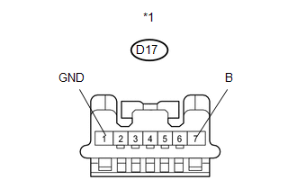
*1 |
Front view of wire harness connector (to Steering Lock ECU (Steering Lock Actuator Assembly)) |
| NG | .gif) |
REPAIR OR REPLACE HARNESS OR CONNECTOR |
|
.gif)
|
2. |
CHECK HARNESS AND CONNECTOR (CERTIFICATION ECU - STEERING LOCK ECU) |
|
(a) Disconnect the D25 ECU connector. |
|
(b) Measure the resistance according to the value(s) in the table below.
Standard Resistance:
|
Tester Connection |
Condition |
Specified Condition |
|---|---|---|
|
D25-29 (LIN) - D17-5 (LIN) |
Always |
Below 1 Ω |
|
D25-29 (LIN) - Body ground |
Always |
10 kΩ or higher |
|
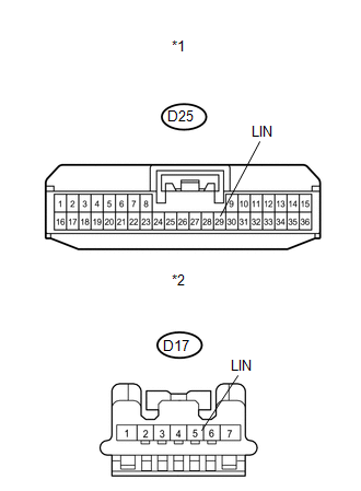
*1 |
Front view of wire harness connector (to Certification ECU (Smart Key ECU Assembly)) |
|
*2 |
Front view of wire harness connector (to Steering Lock ECU (Steering Lock Actuator Assembly)) |
| NG | |
REPAIR OR REPLACE HARNESS OR CONNECTOR |
|
|
3. |
REPLACE STEERING LOCK ECU (STEERING LOCK ACTUATOR ASSEMBLY) |
(a) Replace the steering lock ECU (steering lock actuator assembly) (See page
.gif) ).
).
|
|
4. |
CHECK DTC OUTPUT |
(a) Clear the DTC (See page ).
(b) Recheck for DTCs.
OK:
DTC B2786 is not output.
| OK | |
END (STEERING LOCK ECU WAS DEFECTIVE) |
| NG | |
REPLACE CERTIFICATION ECU (SMART KEY ECU ASSEMBLY) |
 Diagnostic Trouble Code Chart
DIAGNOSTIC TROUBLE CODE CHART
Main Body ECU (Driver Side junction Block Assembly)
DTC Code
Detection Item
Trouble Area
See page
B1206
...
 Lost Communication with Automatic High Beam Sensor (B2432)
DESCRIPTION
Refer to DTC B2432 (Lighting system) (See page
).
DTC No.
DTC Detection Condition
Trouble Area
B2432
Malfunction in LIN com ...
Other materials about Toyota Venza:
Replacement
REPLACEMENT
CAUTION / NOTICE / HINT
CAUTION:
Prolonged and repeated contact with engine oil will result in the removal
of natural oils from the skin, leading to dryness, irritation and dermatitis.
In addition, used engine oil contains potent ...
Slide Sensor Malfunction (B2650)
DESCRIPTION
When the position control ECU and switch assembly does not receive a sensor signal
despite forward or backward movement of seat by power seat motor operation, this
DTC is output.
DTC Code
DTC Detection Condition
...
Parking Brake Switch Circuit
DESCRIPTION
This circuit is from the parking brake switch assembly to the radio and display
receiver assembly.
WIRING DIAGRAM
PROCEDURE
1.
CHECK BRAKE WARNING LIGHT
(a) Check that the brake warning light comes on when t ...

0.1729