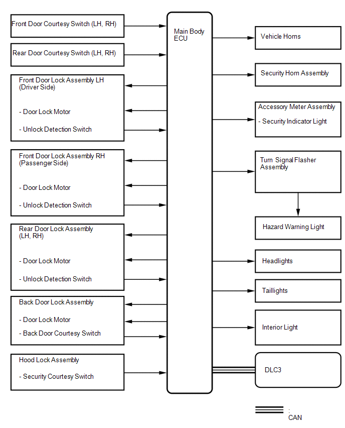
Toyota Venza: System Diagram
SYSTEM DIAGRAM
 Precaution
PRECAUTION
1. NOTICE FOR INITIALIZATION
CAUTION:
When disconnecting the cable from the negative (-) battery terminal, initialize
the following system after the cable is reconnected.
S ...
 How To Proceed With Troubleshooting
CAUTION / NOTICE / HINT
HINT:
Use this procedure to troubleshoot the theft deterrent system.
*: Use the Techstream.
PROCEDURE
1.
VEHICLE BROUGHT TO WORKSHO ...
Other materials about Toyota Venza:
Back Door Entry Unlock Function does not Operate
DESCRIPTION
If the entry back door open function does not operate but the back door entry
lock function operates, the communication between the vehicle and key is normal.
As a faulty part, the back door open switch circuit (from the back door opener switc ...
Speaker Circuit
DESCRIPTION
If there is a short in a speaker circuit, the radio and display receiver
assembly detects it and stops output to the speakers.
Thus sound cannot be heard from the speakers even if there is no malfunction
in the radio and display ...
System Description
SYSTEM DESCRIPTION
1. FUNCTION DESCRIPTION
(a) Steering Cooperative Control
(1) Enhanced-VSC performs coordinated control consisting of VSC and electronic
power steering. By integrating these preventive safety functions, Enhanced-VSC ensures
excellent d ...

0.1143