Toyota Venza: System Diagram
SYSTEM DIAGRAM
|
Transmitting ECU (Transmitter) |
Receiving ECU |
Signal |
Communication Method |
|---|---|---|---|
|
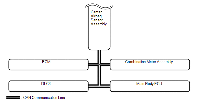
Center Airbag Sensor Assembly |
ECM |
Crash detection signal |
CAN |
|
Combination Meter Assembly |
|
||
|
Main Body ECU |
Driver seat buckle switch signal |
||
|
ECM |
Center Airbag Sensor Assembly |
|
|
|
Combination Meter Assembly |
Vehicle speed signal |
 Parts Location
PARTS LOCATION
ILLUSTRATION
ILLUSTRATION
...
 How To Proceed With Troubleshooting
CAUTION / NOTICE / HINT
HINT:
*: Use the Techstream.
PROCEDURE
1.
VEHICLE BROUGHT TO WORKSHOP
NEXT
...
Other materials about Toyota Venza:
Installation
INSTALLATION
PROCEDURE
1. INSTALL MANUAL VALVE
(a) Coat the manual valve with ATF and install it to the transmission
valve body assembly.
2. INSTALL TRANSMISSION VALVE BODY ASSEMBLY
(a) Coat th ...
System Description
SYSTEM DESCRIPTION
1. PUSH-BUTTON START DESCRIPTION
(a) The push-button start uses a push-type engine switch, which the driver can
operate by merely carrying the electrical key. This system consists primarily of
the power management control ECU, engine s ...
Freeze Frame Data
FREEZE FRAME DATA
1. FREEZE FRAME DATA
NOTICE:
Freeze frame data values will vary depending on the measurement conditions,
surroundings, or vehicle conditions. For this reason, there may be a problem
even when the values are within specifica ...

0.1597