Toyota Venza: Installation
INSTALLATION
CAUTION / NOTICE / HINT
HINT:
- Use the same procedure for the RH side and LH side.
- The procedure listed below is for the LH side.
PROCEDURE
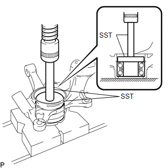
1. INSTALL FRONT AXLE HUB BEARING
|
(a) Using SST and a press, install a new front axle hub bearing to the steering knuckle. SST: 09950-60020 09951-00810 SST: 09950-70010 09951-07100 |
|
2. INSTALL FRONT DISC BRAKE DUST COVER
|
(a) Install the front disc brake dust cover to the steering knuckle with the 4 bolts. Torque: 8.3 N·m {85 kgf·cm, 73 in·lbf} |
|
.png)
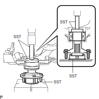
3. INSTALL FRONT AXLE HUB SUB-ASSEMBLY
|
(a) Using SST and a press, install the front axle hub sub-assembly to the steering knuckle. SST: 09608-32010 SST: 09950-60010 09951-00620 SST: 09950-70010 09951-07100 |
|
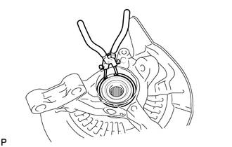
4. INSTALL FRONT AXLE HUB HOLE SNAP RING
|
(a) Using snap ring pliers, install a new front axle hub hole snap ring. |
|
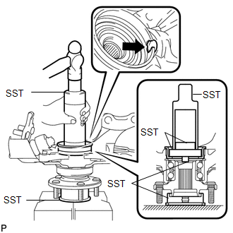
5. INSTALL FRONT NO. 1 WHEEL BEARING DUST DEFLECTOR
|
(a) Using SST and a hammer, install a new front No. 1 wheel bearing dust deflector. SST: 09316-60011 09316-00011 SST: 09608-32010 SST: 09950-60010 09951-00500 SST: 09950-60020 09951-00810 09952-06010 HINT: Align the cutout for the speed sensor in the No. 1 front wheel bearing dust deflector with the hole of the steering knuckle. |
|
6. INSTALL FRONT AXLE ASSEMBLY
(a) Apply a total of 0.1 to 0.3g (0.00353 to 0.0105 oz.) of Toyota Body Grease W to the 8 areas shown in the illustration.
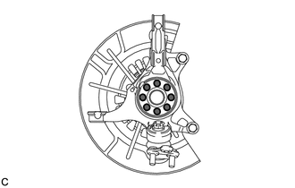 Text in Illustration
 |
Toyota Body Grease W |
NOTICE:
Do not apply grease to the serrations or installation hole of the front speed sensor.
|
(b) Install the front axle assembly to the front shock absorber with the 2 bolts and 2 nuts. Torque: 290 N·m {2956 kgf·cm, 214 ft·lbf} NOTICE: When installing the nuts, keep the bolts from rotating. |
|
.png)
7. INSTALL FRONT DRIVE SHAFT ASSEMBLY
|
(a) Align the matchmarks and install the front drive shaft assembly to the front axle hub sub-assembly. Text in Illustration
|
|
.png)
8. INSTALL FRONT LOWER SUSPENSION ARM
|
(a) Install the front lower suspension arm to the front lower ball joint with the bolt and 2 nuts. Torque: 92 N·m {938 kgf·cm, 68 ft·lbf} |
|
.png)
9. CONNECT TIE ROD ASSEMBLY
.gif)
10. INSTALL FRONT DISC
11. INSTALL FRONT DISC BRAKE CALIPER ASSEMBLY
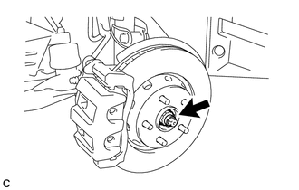
12. INSTALL FRONT AXLE SHAFT NUT
(a) Clean the threaded parts on the front drive shaft assembly and a new front axle shaft nut using a non-residue solvent.
NOTICE:
- Be sure to perform this work for a new front drive shaft assembly.
- Keep the threaded parts free of oil and foreign matter.
|
(b) Using a socket wrench (30 mm), install the new front axle shaft nut. Torque: 294 N·m {2998 kgf·cm, 217 ft·lbf} NOTICE: Stake the front axle shaft nut after inspecting for looseness and runout in the following steps. HINT: Keep depressing the brake pedal to prevent the drive shaft from rotating. |
|
13. SEPARATE FRONT DISC BRAKE CALIPER ASSEMBLY
14. REMOVE FRONT DISC
15. INSPECT FRONT AXLE HUB BEARING LOOSENESS
16. INSPECT FRONT AXLE HUB RUNOUT
17. INSTALL FRONT DISC
18. INSTALL FRONT DISC BRAKE CALIPER ASSEMBLY
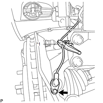
19. INSTALL FRONT SPEED SENSOR
|
(a) Install the resin clamp and front speed sensor with the bolt. Text in Illustration
Torque: 8.5 N·m {87 kgf·cm, 75 in·lbf} NOTICE:
|
|
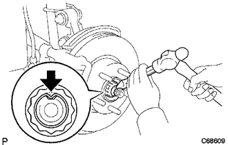
20. STAKE FRONT AXLE SHAFT NUT
|
(a) Using a chisel and hammer, stake the front axle shaft nut. |
|
21. INSTALL FRONT WHEEL
Torque:
103 N·m {1050 kgf·cm, 76 ft·lbf}
22. INSPECT AND ADJUST FRONT WHEEL ALIGNMENT
(a) Inspect and adjust the front wheel alignment (See page
).
23. CHECK FOR SPEED SENSOR SIGNAL
(a) Check for the speed sensor signal (See page
).
 Removal
REMOVAL
CAUTION / NOTICE / HINT
HINT:
Use the same procedure for the RH side and LH side.
The procedure listed below is for the LH side.
PROCEDURE
1. REMOVE FRONT WHEEL
2. REMO ...
 Front Axle Hub Bolt
Components
COMPONENTS
ILLUSTRATION
Replacement
REPLACEMENT
CAUTION / NOTICE / HINT
HINT:
Use the same procedure for the RH side and LH side.
The procedure listed below is for ...
Other materials about Toyota Venza:
Disposal
DISPOSAL
PROCEDURE
1. DISPOSE OF FRONT SHOCK ABSORBER ASSEMBLY
(a) Position the front shock absorber assembly level with the piston
rod fully extended. Using a drill, make a hole in the cylinder between A
and B as shown in the illustratio ...
Antenna Coil Open / Short (B2784)
DESCRIPTION
The transponder key coil is built into the transponder key amplifier and receives
a key code signal from the transponder chip in the key. This signal is amplified
by the amplifier, then it is output to the transponder key ECU assembly.
...
Air Conditioning Amplifier Communication Stop Mode
DESCRIPTION
Detection Item
Symptom
Trouble Area
Air Conditioning Amplifier Communication Stop Mode
"Air Conditioner" is not displayed on "CAN Bus Check" screen
o ...

0.1601