Toyota Venza: System Diagram
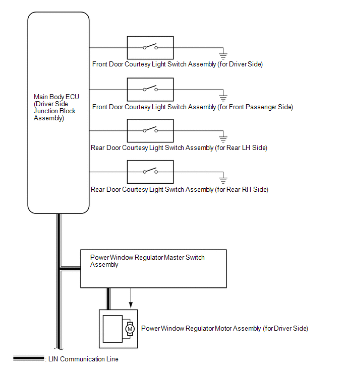
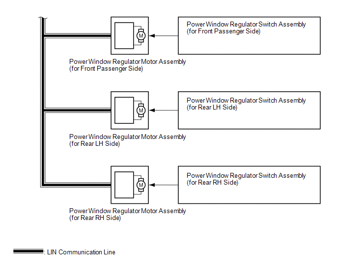
SYSTEM DIAGRAM
 Communication Table
|
Transmitting ECU |
Receiving ECU |
Signal |
Communication Method |
|---|---|---|---|
|
Power window regulator master switch assembly |
Power window regulator motor assembly (for driver side) |
Power window auto up and down signal |
LIN |
|
Power window remote up and down signal |
LIN |
|
|
Main body ECU (driver side junction block assembly) |
|
Power window operation permission signal |
LIN |
 Parts Location
PARTS LOCATION
ILLUSTRATION
ILLUSTRATION
...
 How To Proceed With Troubleshooting
CAUTION / NOTICE / HINT
HINT:
Use the following procedure to troubleshoot the power window control
system.
*: Use the Techstream.
PROCEDURE
1.
VEHICLE ...
Other materials about Toyota Venza:
System Description
SYSTEM DESCRIPTION
1. GENERAL
(a) Deceleration sensors used for the airbag system are installed on various
parts on the vehicle and calculate the deceleration rate of each part during a collision.
(b) Depending on the situation, the center airbag sensor a ...
Afs Ecu
Components
COMPONENTS
ILLUSTRATION
Installation
INSTALLATION
PROCEDURE
1. INSTALL AFS ECU
(a) Engage the guide.
(b) Install the AFS ECU with the bolt.
(c) Connect the connector.
2. INSTA ...
On-vehicle Inspection
ON-VEHICLE INSPECTION
PROCEDURE
1. CHECK BATTERY CONDITION
NOTICE:
If the battery is weak or if the engine is difficult to start, perform the following
procedure.
(a) Check the battery for damage and deformation. If severe damage, deformation
or leaka ...

0.1461