Toyota Venza: Parts Location
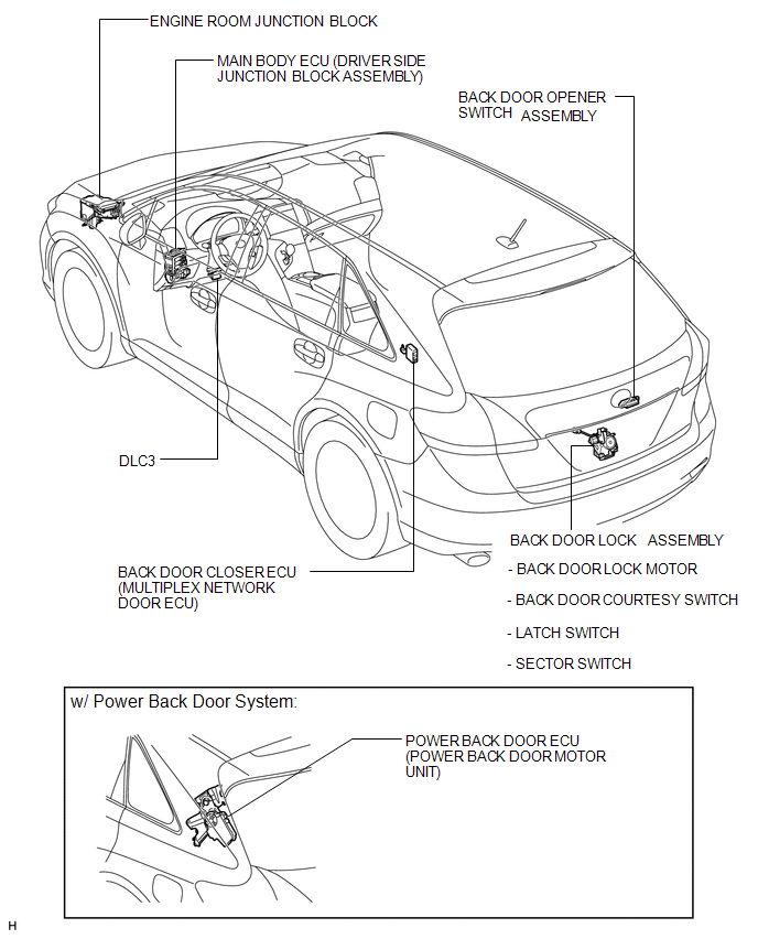
PARTS LOCATION
ILLUSTRATION
 Precaution
PRECAUTION
NOTICE:
When disconnecting the cable from the negative (-) battery terminal, initialize
the following systems after the cable is reconnected.
System Name
See Proc ...
 System Diagram
SYSTEM DIAGRAM
Communication Method
Transmitting ECU
Receiver
Signal
Communication Method
Main body ECU (Driver Side Junction Block Asse ...
Other materials about Toyota Venza:
Jam Protection Function Activates During Power Back Door Operation
DESCRIPTION
When the jam protection function activates during power back door operation,
one of the following may be the cause: 1) improper fit of back door, or a foreign
object is stuck in the back door, 2) malfunctioning power back door touch sensor
c ...
Short in Curtain Shield Squib LH Circuit (B1835/58-B1838/58)
DESCRIPTION
The curtain shield squib LH circuit consists of the center airbag sensor assembly
and curtain shield airbag assembly LH.
The center airbag sensor assembly uses this circuit to deploy the airbag when
deployment conditions are met.
These DTCs ...
Door Courtesy Switch Circuit
DESCRIPTION
The main body ECU (driver side junction block assembly) detects the condition
of the door courtesy light switch.
WIRING DIAGRAM
PROCEDURE
1.
READ VALUE USING TECHSTREAM
(a) Connect the Techstream to the DLC3 ...

0.1713