Toyota Venza: System Diagram
SYSTEM DIAGRAM
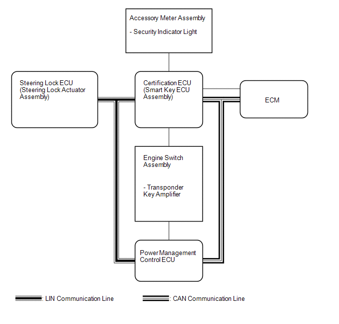 Input and Output Signal of Each ECU
|
Transmitting ECU (transmitter) |
Receiving ECU |
Signal |
Communication Method |
|---|---|---|---|
|
Power management Control ECU |
Steering Lock ECU (Steering Lock Actuator Assembly) |
Power supply status (to steering lock motor) |
LIN |
|
Steering Lock ECU (Steering Lock Actuator Assembly) |
Certification ECU (Smart Key ECU Assembly) |
Sleep available status |
LIN |
|
Steering Lock ECU (Steering Lock Actuator Assembly) |
|
Lock/Unlock sensor status |
LIN |
|
Steering Lock ECU (Steering Lock Actuator Assembly) |
Certification ECU (Smart Key ECU Assembly) |
Steering lock status |
LIN |
|
Steering Lock ECU (Steering Lock Actuator Assembly) |
Certification ECU (Smart Key ECU Assembly) |
Motor control status |
LIN |
|
Steering Lock ECU (Steering Lock Actuator Assembly) |
Certification ECU (Smart Key ECU Assembly) |
Diagnostic response status |
LIN |
|
Steering Lock ECU (Steering Lock Actuator Assembly) |
Certification ECU (Smart Key ECU Assembly) |
Lock/Unlock sensor malfunction |
LIN |
|
Steering Lock ECU (Steering Lock Actuator Assembly) |
Certification ECU (Smart Key ECU Assembly) |
Power supply malfunction (to steering lock motor) |
LIN |
|
Steering Lock ECU (Steering Lock Actuator Assembly) |
Certification ECU (Smart Key ECU Assembly) |
Motor driver malfunction |
LIN |
|
Steering Lock ECU (Steering Lock Actuator Assembly) |
|
Lock bar (stuck) status |
LIN |
|
Steering Lock ECU (Steering Lock Actuator Assembly) |
|
Push start status |
LIN |
|
Steering Lock ECU (Steering Lock Actuator Assembly) |
Certification ECU (Smart Key ECU Assembly) |
Lock/Unlock relay drive status |
LIN |
|
Steering Lock ECU (Steering Lock Actuator Assembly) |
|
Engine start control status |
LIN |
 System Description
SYSTEM DESCRIPTION
1. DESCRIPTION
(a) The steering lock system locks/unlocks the steering when by activating the
steering lock bar with a motor. The steering lock ECU (steering lock actuator assem ...
 How To Proceed With Troubleshooting
CAUTION / NOTICE / HINT
HINT:
Perform troubleshooting in accordance with the following flowchart.
*: Use the Techstream.
PROCEDURE
1.
VEHICLE BROUGHT TO ...
Other materials about Toyota Venza:
Diagnostic Trouble Code Chart
DIAGNOSTIC TROUBLE CODE CHART
ACTIVE TORQUE CONTROL 4WD SYSTEM
DTC Code
Detection Item
Trouble Area
See page
C1241/94
Low Power Supply Voltage
1. Battery
2. ECU-IG1 fuse
...
Combination Meter
Components
COMPONENTS
ILLUSTRATION
Disassembly
DISASSEMBLY
PROCEDURE
1. REMOVE COMBINATION METER GLASS
(a) Disengage the 9 claws to remove the combination meter glass.
Removal
REMOVAL
...
Installation
INSTALLATION
PROCEDURE
1. INSTALL INSTRUMENT PANEL WIRE ASSEMBLY
(a) Connect the vent hole connector of the instrument panel wire to the
front passenger airbag assembly.
Text in Illustration
*1
Vent Hol ...

0.1159