Toyota Venza: Starting System
Parts Location
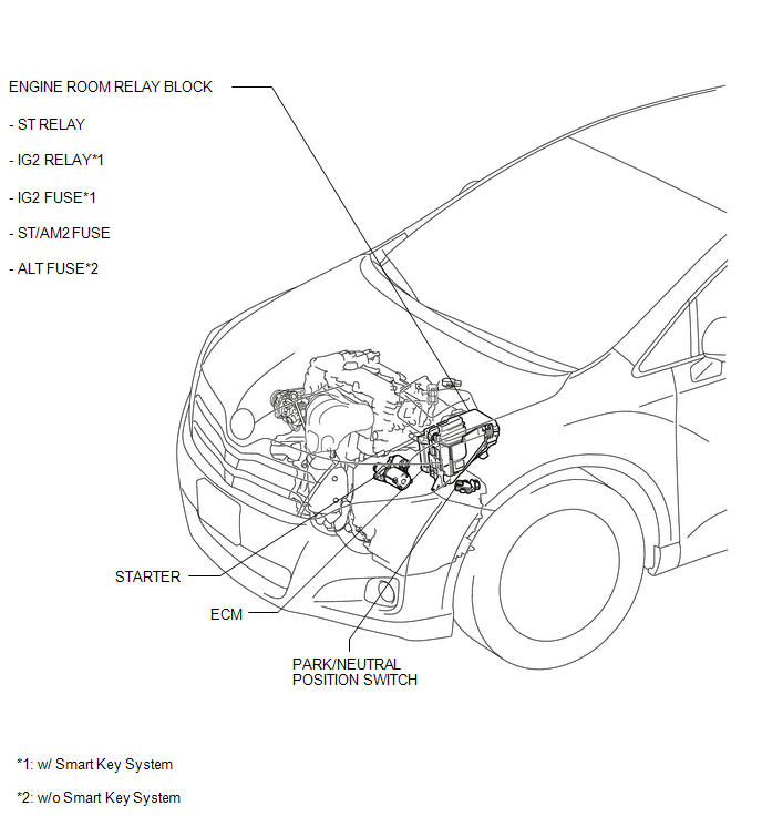
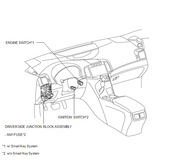
PARTS LOCATION
ILLUSTRATION
ILLUSTRATION
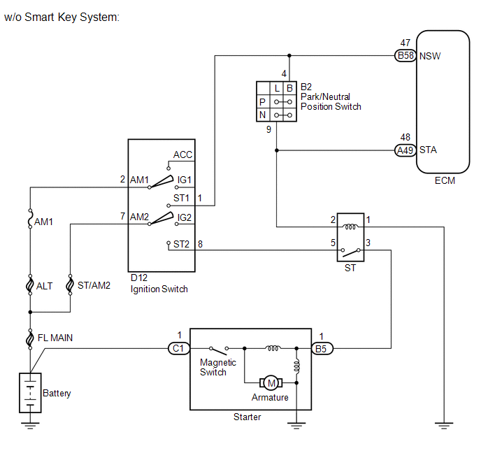
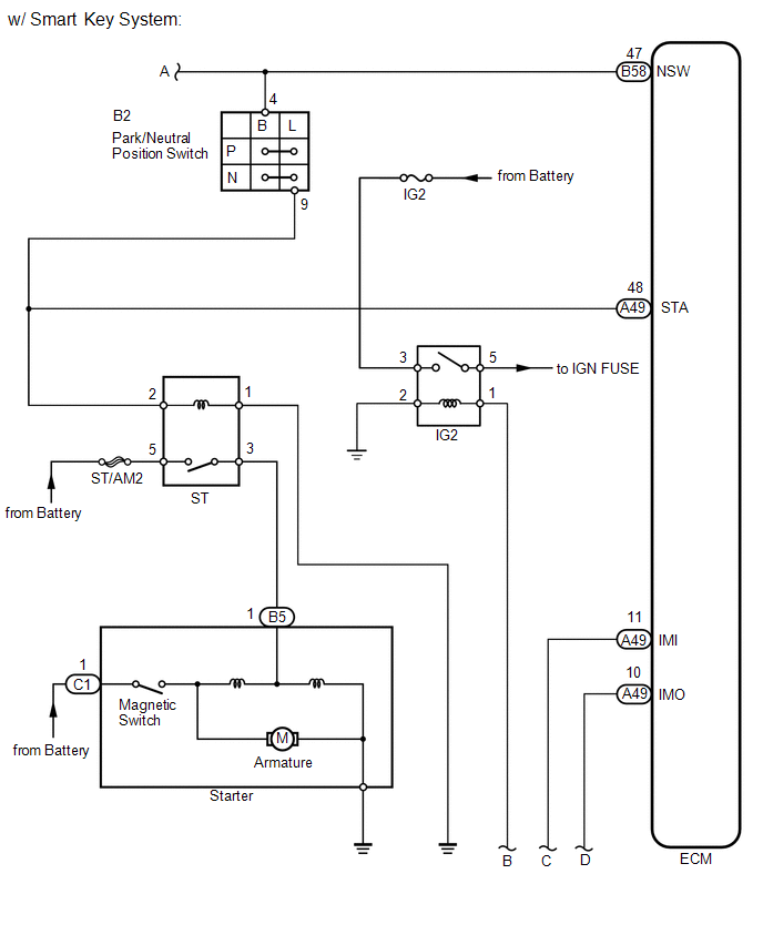
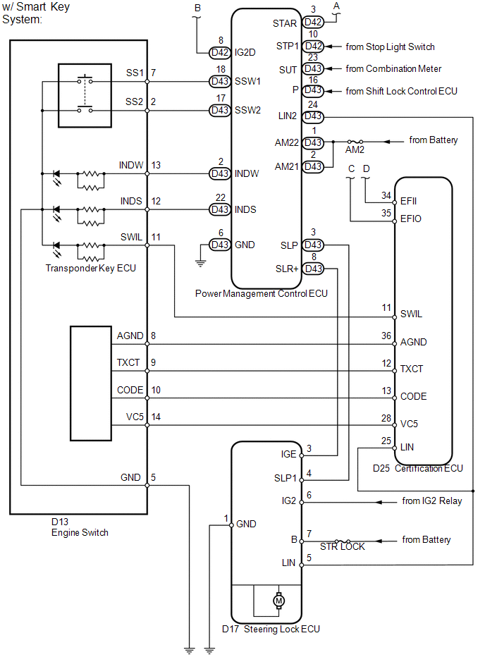
System Diagram
SYSTEM DIAGRAM
 Installation
INSTALLATION
PROCEDURE
1. INSTALL STARTER ASSEMBLY
(a) Install the starter with the 2 bolts.
Torque:
37 N·m {377 kgf·cm, 27 ft·lbf}
...
 Cruise Control
...
Other materials about Toyota Venza:
Adjustment
ADJUSTMENT
CAUTION / NOTICE / HINT
HINT:
Centering bolts are used to mount the hood hinge and hood lock. The
hood and hood lock cannot be adjusted with the centering bolts installed.
Substitute the centering bolts with standard bolts when ...
Inspection
INSPECTION
PROCEDURE
1. INSPECT COMPRESSOR AND MAGNETIC CLUTCH (A/C LOCK SENSOR)
(a) Measure the resistance according to the value(s) in the table below.
Standard Resistance:
Tester Connection
Condition
...
Disassembly
DISASSEMBLY
PROCEDURE
1. DISCONNECT CABLE FROM NEGATIVE BATTERY TERMINAL
NOTICE:
When disconnecting the cable, some systems need to be initialized after the cable
is reconnected (See page ).
2. REMOVE REAR DOOR INSIDE HANDLE BEZEL PLUG
(a) ...

0.1384