Toyota Venza: Reverse Signal Circuit
DESCRIPTION
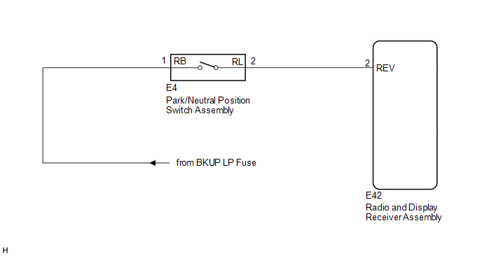
The radio and display receiver assembly receives a reverse signal from the park/neutral position switch assembly.
WIRING DIAGRAM
PROCEDURE
|
1. |
CHECK BACK-UP LIGHT |
(a) Move the shift lever to R and check if the back-up lights come on.
OK:
The back-up lights come on.
| NG | .gif) |
GO TO LIGHTING SYSTEM |
|
.gif)
|
2. |
CHECK HARNESS AND CONNECTOR (REVERSE SIGNAL) |
(a) Disconnect the E42 radio and display receiver assembly connector.
(b) Measure the voltage according to the value(s) in the table below.
Standard Voltage:
|
Tester Connection |
Condition |
Specified Condition |
|---|---|---|
|
E42-2 (REV) - Body ground |
Ignition switch ON Shift lever in R |
11 to 14 V |
|
E42-2 (REV) - Body ground |
Ignition switch ON Shift lever in any position other than R |
Below 1 V |
| OK | |
PROCEED TO NEXT SUSPECTED AREA SHOWN IN PROBLEM SYMPTOMS TABLE |
| NG | |
REPAIR OR REPLACE HARNESS OR CONNECTOR |
 Data Signal Circuit between Radio Receiver and Extension Module
DESCRIPTION
The stereo component tuner assembly sends the image data signal to the radio
and display receiver assembly via this circuit.
WIRING DIAGRAM
PROCEDURE
1.
CHEC ...
 Microphone Circuit between Microphone and Radio Receiver
DESCRIPTION
The radio and display receiver assembly and inner rear view mirror assembly (amplifier
microphone assembly) are connected to each other using the microphone connection
detection signa ...
Other materials about Toyota Venza:
Inspection
INSPECTION
PROCEDURE
1. INSPECT TIE ROD ASSEMBLY LH
(a) Secure the tie rod assembly LH in a vise.
(b) Install the nut to the stud bolt.
(c) Flip the ball joint back and forth 5 times.
(d) Set a to ...
Operation Check
OPERATION CHECK
1. SMART KEY SYSTEM OPERATION INSPECTION
(a) Check the entry unlock function.
(1) Use the wireless lock operation to lock the doors. With the key outside the
vehicle, touch a front door outside handle assembly (touch sensor) and check that ...
Outside Vehicle
General Maintenance
GENERAL MAINTENANCE
CAUTION / NOTICE / HINT
These are maintenance and inspection items that are considered to be
the owner's responsibility.
The owner can do them or they can have them done at a service center.
The ...

0.1562