Toyota Venza: Reverse Shift-linked Function of Power Mirrors does not Operate
SYSTEM DESCRIPTION
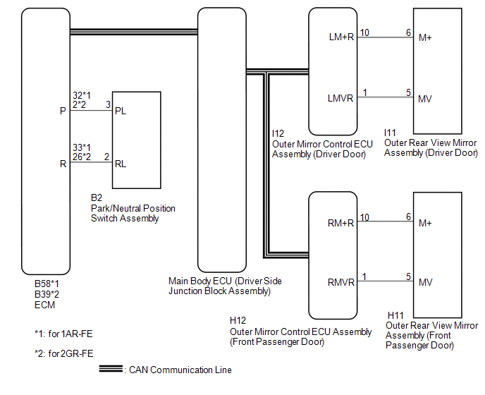
On receiving a reverse signal from the park/neutral position switch assembly, the ECM sends the reverse signal to the main body ECU (driver side junction block assembly) via CAN communication. When receiving the reverse signal, the main body ECU (driver side junction block assembly) sends the reverse request signal to each outer mirror control ECU. Each outer mirror control ECU then performs control in response to the reverse signal.
HINT:
The reverse shift-linked function will not activate when the mirror select switch is in the neutral position (off).
WIRING DIAGRAM
CAUTION / NOTICE / HINT
HINT:
The reverse shift-linked function will not activate when the mirror select switch is in the neutral position (off).
PROCEDURE
|
1. |
CHECK MEMORY AND REACTIVATION FUNCTION |
|
(a) Turn the ignition switch ON. |
|
.png)
(b) Using the outer mirror switch assembly, turn the mirror surface to the fully left position.
(c) Press the M1 switch while the SET switch is being pressed.
(d) Check that the buzzer sounds for 0.5 seconds and the mirror surface position is memorized.
(e) Using the outer mirror switch assembly, turn the mirror surface to the fully right position.
(f) Press the M1 switch.
(g) Check that the buzzer sounds for 0.1 seconds and the outer mirror automatically moves to the recorded fully left position.
|
Result |
Proceed to |
|---|---|
|
Memory and reactivation functions are normal. |
A |
|
Memory function is not normal. |
B |
|
Reactivation function is not normal. |
C |
|
*a |
Turn to Left Fully |
| B | .gif) |
GO TO OTHER DIAGNOSIS PROCEDURE (Power Mirror Surface Position is not Memorized) |
| C | |
GO TO OTHER DIAGNOSIS PROCEDURE (Power Mirrors do not Return to Memorized Position) |
|
.gif)
|
2. |
CHECK CAN COMMUNICATION SYSTEM |
(a) Use the Techstream to check if the CAN communication system is functioning
normally (See page .gif) ).
).
OK:
CAN communication DTC is not output.
| NG | |
GO TO CAN COMMUNICATION SYSTEM (DIAGNOSTIC TROUBLE CODE CHART) |
|
|
3. |
CHECK FOR DTC |
(a) Connect the Techstream to the DLC3.
(b) Turn the ignition switch ON.
(c) Turn the Techstream on.
(d) Enter the following menus: Powertrain / Engine / DTC.
(e) Check if SFI system DTCs are output.
OK:
SFI system DTCs are not output.
|
Result |
Proceed to |
|---|---|
|
OK |
A |
|
NG (for 1AR-FE) |
B |
|
NG (for 2GR-FE) |
C |
| B | |
GO TO SFI SYSTEM (for 1AR-FE) (DIAGNOSTIC TROUBLE CODE CHART) |
| C | |
GO TO SFI SYSTEM (for 2GR-FE) (DIAGNOSTIC TROUBLE CODE CHART) |
|
|
4. |
CHECK COMBINATION METER ASSEMBLY |
(a) Check if the shift position indicator light in the combination meter assembly operates normally.
OK:
The shift position indicator light indicates the actual shift position correctly.
| NG | |
GO TO METER / GAUGE SYSTEM (PROBLEM SYMPTOMS TABLE) |
|
|
5. |
CHECK REVERSE SHIFT-LINKED FUNCTION |
|
(a) Turn the ignition switch ON. |
|
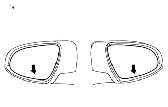
(b) Set the mirror select switch to L or R.
(c) Check that the mirror surface turns downward when the shift lever is moved to R.
|
Result |
Proceed to |
|---|---|
|
Reverse shift-linked functions on both mirrors are not normal |
A |
|
Reverse shift-linked function on driver door is not normal |
B |
|
Reverse shift-linked function on front passenger door is not normal |
C |
|
*a |
Downward |
| A | |
REPLACE MAIN BODY ECU (DRIVER SIDE JUNCTION BLOCK ASSEMBLY) |
| B | |
REPLACE OUTER MIRROR CONTROL ECU ASSEMBLY (DRIVER DOOR) |
| C | |
REPLACE OUTER MIRROR CONTROL ECU ASSEMBLY (FRONT PASSENGER DOOR) |
 Power Mirrors do not Return to Memorized Position
SYSTEM DESCRIPTION
If either the M1 or M2 seat memory switch is pressed, the outer mirror control
ECU assembly (driver door) detects the seat memory switch status and sends the switch
signal to t ...
 Wireless Transmitter Memory Function does not Operate
DESCRIPTION
Key IDs can be registered (linked) with either the M1 or M2 seat memory switches.
The key ID registration procedure should be performed while the electrical key transmitter
sub-assemb ...
Other materials about Toyota Venza:
Data Signal Circuit between Navigation Receiver Assembly and Extension Module
DESCRIPTION
The stereo component tuner assembly sends the image data signal to the navigation
receiver assembly via this circuit.
WIRING DIAGRAM
PROCEDURE
1.
CHECK NAVIGATION WIRE
(a) Remove the navigation wire (See pag ...
Removal
REMOVAL
PROCEDURE
1. REMOVE WINDSHIELD WIPER MOTOR AND LINK
(a) Remove the windshield wiper motor and link (See page
).
2. REMOVE OUTER COWL TOP PANEL SUB-ASSEMBLY
3. REMOVE COOL AIR INTAKE DUCT SEAL
4. REMOVE NO. 1 ENGINE COVER SUB-ASSEMBLY
...
Installation
INSTALLATION
PROCEDURE
1. INSTALL DOOR CONTROL RECEIVER
(a) Install the door control receiver with the bolt.
(b) Connect the connector.
2. INSTALL ROOF SIDE INNER GARNISH ASSEMBLY RH
HINT:
Use th ...

0.1393