Toyota Venza: Repair
REPAIR
PROCEDURE
1. REPAIR INTAKE VALVE SEAT
NOTICE:
- Repair the seat while checking the seating position.
- Keep the lip free of foreign matter.
- Take off the cutter gradually to make the intake valve seat smooth.
|
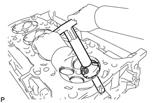
(a) Using a 45° cutter, resurface the valve seat so that the valve seat width is more than the specification. |
|
|
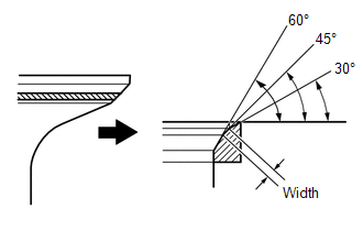
(b) Using 30° and 60° cutters, correct the valve seat so that the valve contacts the entire circumference of the seat. The contact should be in the center of the valve seat, and the valve seat width should be maintained within the specified range around the entire circumference of the seat. Standard width: 1.0 to 1.4 mm (0.0394 to 0.0551 in.) |
|
(c) Hand-lap the valve and valve seat with an abrasive compound.
(d) Check the valve seating position.
2. REPAIR EXHAUST VALVE SEAT
NOTICE:
- Repair the seat while checking the seating position.
- Keep the lip free of foreign matter.
- Take off the cutter gradually to make the exhaust valve seat smooth.
|
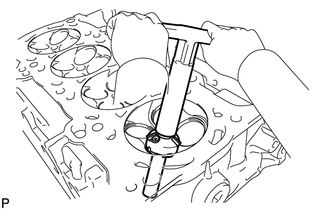
(a) Using a 45° cutter, resurface the valve seat so that the valve seat width is more than the specification. |
|
|
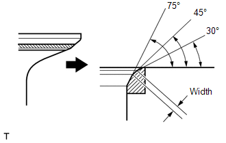
(b) Using 30° and 75° cutters, correct the valve seat so that the valve contacts the entire circumference of the seat. The contact should be in the center of the valve seat, and the valve seat width should be maintained within the specified range around the entire circumference of the seat. Standard width: 1.2 to 1.6 mm (0.0472 to 0.0630 in.) |
|
(c) Hand-lap the valve and valve seat with an abrasive compound.
(d) Check the valve seating position.
 Reassembly
REASSEMBLY
CAUTION / NOTICE / HINT
HINT:
Perform "Inspection After Repair" after replacing the cylinder head sub-assembly
(See page ).
PROCEDURE
1. INSTALL SPARK PLUG TUBE
HINT:
Wh ...

Other materials about Toyota Venza:
System Diagram
SYSTEM DIAGRAM
Transmitting ECU
(Transmitter)
Receiving ECU
Signal
Communication Method
ECM
Power Steering ECU
Engine speed signal
Engine variation inform ...
Dtc Check / Clear
DTC CHECK / CLEAR
1. DTC CHECK (USING SST CHECK WIRE)
(a) Check the DTCs (Current trouble codes).
(1) Turn the ignition switch to ON, and wait for approximately 60 seconds.
(2) Using SST, connect terminals TC and CG of the DLC3.
SST: 09843-18040
NOTICE ...
Removal
REMOVAL
CAUTION / NOTICE / HINT
HINT:
Use the same procedure for the RH side and LH side.
The procedure listed below is for the LH side.
PROCEDURE
1. PRECAUTION
CAUTION:
Be sure to read Precaution thoroughly before servicing (See page
...

0.1389