Toyota Venza: Reassembly
REASSEMBLY
CAUTION / NOTICE / HINT
HINT:
Perform "Inspection After Repair" after replacing the cylinder head sub-assembly
(See page .gif) ).
).
PROCEDURE
1. INSTALL SPARK PLUG TUBE
HINT:
When using a new cylinder head, the spark plug tubes must be replaced.
|
(a) Apply adhesive onto the shaded area of a new spark plug tube. Adhesive: Toyota Genuine Adhesive 1324, Three Bond 1324 or equivalent. Standard application width: 2.0 mm (0.0787 in.) NOTICE:
|
|
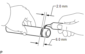
|
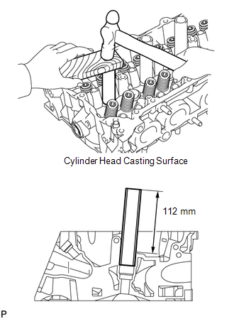
(b) Using a wooden block and hammer, tap in the spark plug tube to the specified protrusion height. Standard protrusion height: 112 mm (4.41 in.) NOTICE: To avoid tapping in the spark plug tube too far, measure the protrusion height while tapping it. |
|
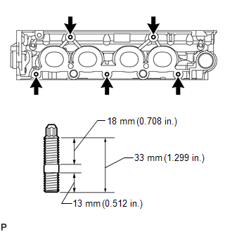
2. INSTALL CYLINDER HEAD STUD BOLT
|
(a) Using an E7 "TORX" socket wrench, install the cylinder head stud bolts. Torque: 6.5 N·m {66 kgf·cm, 58 in·lbf} |
|
3. INSTALL NO. 1 STRAIGHT SCREW PLUG
|
(a) Using a 10 mm hexagon wrench, install 3 new gaskets and the 3 straight screw plugs. Torque: 44 N·m {449 kgf·cm, 32 ft·lbf} |
|
.png)
4. INSTALL NO. 2 STRAIGHT SCREW PLUG
|
(a) Using a 14 mm hexagon wrench, install a new gasket and the straight screw plug. Torque: 78 N·m {795 kgf·cm, 58 ft·lbf} |
|
.png)
5. INSTALL VALVE SPRING SEAT
(a) Install the valve spring seats to the cylinder head.
6. INSTALL VALVE STEM OIL SEAL
(a) Apply a light coat of engine oil to new oil seals.
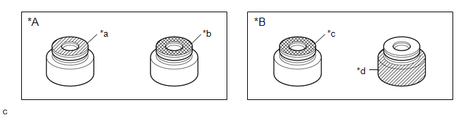 Text in Illustration
|
*A |
for Intake Side |
*B |
for Exhaust Side |
|
*a |
Gray (for Intake Side) |
*b |
Black (for Intake Side) |
|
*c |
Black (for Exhaust Side) |
*d |
Gray (for Exhaust Side) |
NOTICE:
Pay attention when installing the intake and exhaust oil seals. For example, installing the intake oil seal onto the exhaust side or installing the exhaust oil seal onto the intake side can cause installation problems later.
HINT:
- for Intake Side
The intake side valve stem oil seals is gray or black.
- for Exhaust Side
The exhaust side valve stem oil seals is black or gray.
|
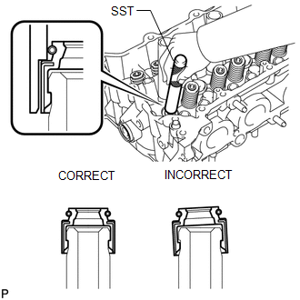
(b) Using SST, push in the intake and exhaust valve oil seals. SST: 09201-41020 NOTICE: Failure to use SST will cause the seal to be damaged or improperly seated. |
|
7. INSTALL INTAKE VALVE
|
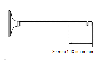
(a) Apply plenty of engine oil to the tip area of the intake valve shown in the illustration. |
|
(b) Install the valve, compression spring and spring retainer to the cylinder head.
NOTICE:
Install the same parts in the same combination to their original locations.
|
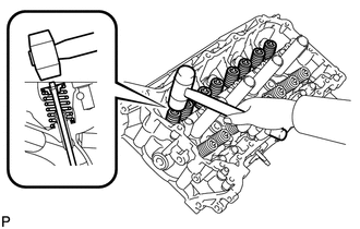
(c) Using SST and wooden blocks, compress the spring and install the retainer locks. SST: 09202-70020 09202-00010 |
|
.png)
|
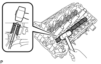
(d) Using a plastic-faced hammer, lightly tap the valve stem tip to ensure a proper fit. NOTICE: Be careful not to damage the retainer. |
|
8. INSTALL EXHAUST VALVE
|
(a) Apply plenty of engine oil to the tip area of the exhaust valve shown in the illustration. |
|
(b) Install the valve, compression spring and spring retainer to the cylinder head.
NOTICE:
Install the same parts in the same combination to their original locations.
|
(c) Using SST and wooden blocks, compress the spring and install the retainer locks. SST: 09202-70020 09202-00010 |
|
.png)
|
(d) Using a plastic-faced hammer, lightly tap the valve stem tip to ensure a proper fit. NOTICE: Be careful not to damage the retainer. |
|
 Replacement
REPLACEMENT
PROCEDURE
1. REPLACE INTAKE VALVE GUIDE BUSH
(a) Heat the cylinder head to approximately 80 to 100°C (176 to 212°F).
(b) Place the cylinder head on wooden blocks.
(c) Usi ...
 Repair
REPAIR
PROCEDURE
1. REPAIR INTAKE VALVE SEAT
NOTICE:
Repair the seat while checking the seating position.
Keep the lip free of foreign matter.
Take off the cutter gradually to make ...
Other materials about Toyota Venza:
Reassembly
REASSEMBLY
PROCEDURE
1. INSTALL FRONT BUMPER SIDE RETAINER LH
(a) Engage the claw and install the front bumper side retainer LH.
Text in Illustration
*1
Bolt
*2
S ...
Terminals Of Ecu
TERMINALS OF ECU
1. CHECK POWER BACK DOOR ECU (POWER BACK DOOR MOTOR UNIT)
(a) Disconnect the L20 ECU connector.
(b) Measure the voltage and resistance according to the value(s) in the table
below.
Tester Connection
Wiring Color
...
Power Source Circuit
DESCRIPTION
1. w/o Multi-information Display
(a) This circuit is the power source circuit for the accessory meter assembly.
This circuit provides two types of power sources; one is a constant power source
mainly used as a backup power source, and the oth ...

0.1147