Toyota Venza: Components
COMPONENTS
ILLUSTRATION
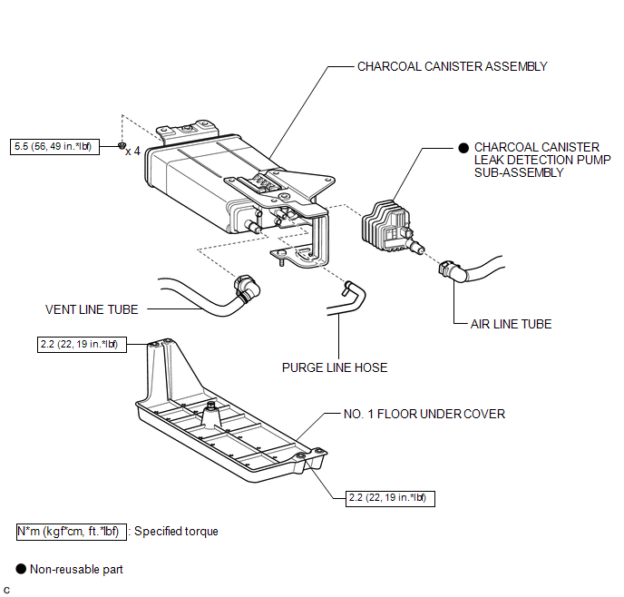
 Canister
...
 Removal
REMOVAL
PROCEDURE
1. REMOVE NO. 1 FLOOR UNDER COVER
(a) Disengage the 4 nuts and clip, and remove the No. 1 floor under cover.
Text in Illustration
Nut (attached to under cov ...
Other materials about Toyota Venza:
All Doors LOCK/UNLOCK Functions do not Operate Via Door Control Switch
DESCRIPTION
The main body ECU (driver side junction block assembly) receives switch signals
from the door control switch and activates the door lock motor on each door according
to these signals.
WIRING DIAGRAM
PROCEDURE
1.
REA ...
Power Source Control ECU Malfunction (B2782)
DESCRIPTION
The power management control ECU controls the power supply to activate the steering
lock motor. This prevents the steering wheel from being locked while the vehicle
is moving.
DTC No.
DTC Detecting Condition
T ...
Inspection
INSPECTION
PROCEDURE
1. INSPECT POWER WINDOW REGULATOR SWITCH ASSEMBLY (for Rear LH)
(a) Check the switch function.
(1) Measure the resistance according to the value(s) in the table below.
Standard Resistance:
Tester Co ...

0.1262