Toyota Venza: Removal
REMOVAL
CAUTION / NOTICE / HINT
HINT:
- Use the same procedure for the RH side and LH side.
- The procedure listed below is for the LH side.
PROCEDURE
1. REMOVE REAR WHEEL
2. SEPARATE REAR SPEED SENSOR
|
(a) Remove the bolt and separate the rear speed sensor from the rear axle carrier sub-assembly. NOTICE: Keep the sensor tip and rear speed sensor installation hole free of foreign matter. |
|
.png)
3. REMOVE REAR AXLE SHAFT NUT
.gif)
4. SEPARATE REAR DISC BRAKE CALIPER ASSEMBLY
5. REMOVE REAR DISC
6. REMOVE REAR AXLE HUB AND BEARING ASSEMBLY
|
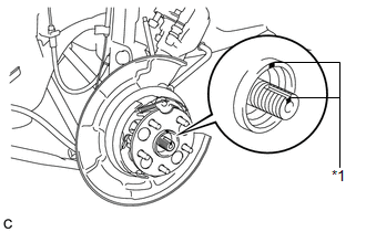
(a) Put matchmarks on the rear drive shaft assembly and rear axle hub and bearing assembly. Text in Illustration
NOTICE: Do not punch the matchmarks. |
|
|
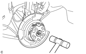
(b) Using a plastic hammer, separate the rear drive shaft assembly from the axle hub and bearing assembly. If it is difficult to separate, tap the end of the rear drive shaft assembly using a brass bar and a hammer. |
|
|
(c) Remove the 4 bolts and the rear axle hub and bearing assembly. NOTICE:
|
|
.png)
 Installation
INSTALLATION
CAUTION / NOTICE / HINT
HINT:
Use the same procedure for the RH side and LH side.
The procedure listed below is for the LH side.
PROCEDURE
1. INSTALL REAR AXLE HUB ...

Other materials about Toyota Venza:
Throttle / Pedal Position Sensor "A" Minimum Stop Performance (P2109)
DESCRIPTION
The idle speed is controlled by the Electronic Throttle Control System (ETCS).
The ETCS is comprised of a throttle actuator, which operates the throttle valve,
and a throttle position sensor, which detects the opening amount of the throttle
...
Installation
INSTALLATION
PROCEDURE
1. INSTALL VACUUM SWITCHING VALVE ASSEMBLY (for ACIS)
(a) Install the vacuum switching valve assembly (for ACIS) with the bolt.
Torque:
9.0 N·m {92 kgf·cm, 80 in·lbf}
...
Front Airbag Sensor LH Malfunction (B1615/14)
DESCRIPTION
The front airbag sensor LH circuit consists of the center airbag sensor assembly
and front airbag sensor LH.
The front airbag sensor LH detects impacts to the vehicle and sends signals to
the center airbag sensor assembly to determine if the ...

0.1382