Toyota Venza: Components
COMPONENTS
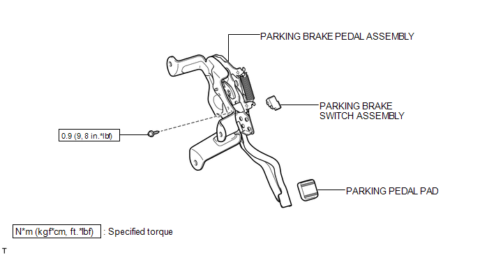
ILLUSTRATION
ILLUSTRATION
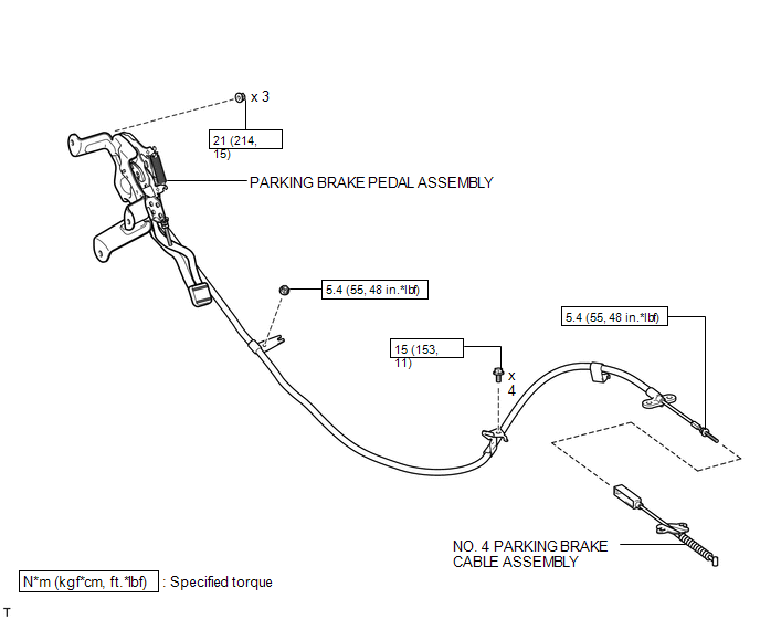
ILLUSTRATION
.png)
ILLUSTRATION

 Removal
REMOVAL
PROCEDURE
1. REMOVE YAW RATE AND ACCELERATION SENSOR
HINT:
Refer to the instructions for Removal of the yaw rate and acceleration sensor
(See page ).
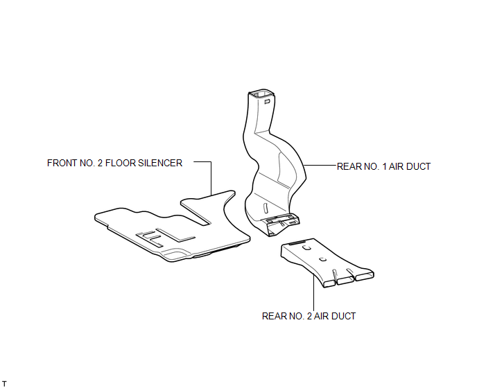
2. REMOVE REAR NO. 2 AIR DUCT
...
Other materials about Toyota Venza:
Removal
REMOVAL
CAUTION / NOTICE / HINT
NOTICE:
Do not replace the spiral cable with the battery connected and the ignition
switch ON.
Do not rotate the spiral cable without the steering wheel with the battery
connected and the ignition switch O ...
On-vehicle Inspection
ON-VEHICLE INSPECTION
PROCEDURE
1. INSPECT SHIFT LOCK CONTROL UNIT ASSEMBLY
(a) Inspect the shift lock operation.
(1) Move the shift lever to P.
(2) Turn the ignition switch off.
(3) Check that the shift lever cannot be moved from P to any other position ...
Transmitter Battery(w/ Smart Key System)
Replacement
REPLACEMENT
PROCEDURE
1. REMOVE TRANSMITTER BATTERY
NOTICE:
Take extra care when handling these precision electronic components.
(a) Push the release hook knob and extract the mechanical key.
...

0.1381