Toyota Venza: Removal
REMOVAL
CAUTION / NOTICE / HINT
NOTICE:
Release the vacuum from the booster by depressing the brake pedal several times. Then remove the brake master cylinder from the brake booster.
PROCEDURE
1. DRAIN BRAKE FLUID
NOTICE:
If brake fluid leaks onto any painted surface, immediately wash it off.
2. REMOVE AIR CLEANER CAP SUB-ASSEMBLY (for 1AR-FE)
.gif)
3. REMOVE AIR CLEANER CAP SUB-ASSEMBLY (for 2GR-FE)
4. REMOVE AIR CLEANER FILTER ELEMENT SUB-ASSEMBLY
5. REMOVE BRAKE MASTER CYLINDER SUB-ASSEMBLY
|
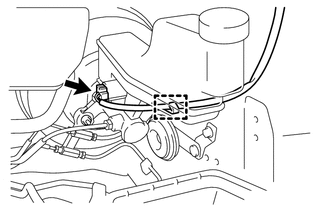
(a) Disconnect the connector and disengage the clamp. |
|
|
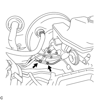
(b) Using a union nut wrench, disconnect the 2 brake lines from the front brake tube way. NOTICE:
|
|
|
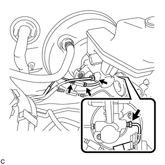
(c) Using a union nut wrench, disconnect the 2 brake lines and remove the No. 1 front brake tube from the brake master cylinder sub-assembly. NOTICE:
|
|
|
(d) Remove the 2 nuts, front brake tube way and brake master cylinder sub-assembly from the brake booster assembly. NOTICE:
|
|
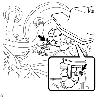
(e) Remove the O-ring from the brake master cylinder sub-assembly.
 Disassembly
DISASSEMBLY
PROCEDURE
1. REMOVE BRAKE MASTER CYLINDER RESERVOIR ASSEMBLY
(a) Mount the brake master cylinder sub-assembly in a vise.
NOTICE:
Place aluminum plates on the vise to prevent damage to ...
 Installation
INSTALLATION
PROCEDURE
1. INSTALL BRAKE MASTER CYLINDER SUB-ASSEMBLY
NOTICE:
When install a new brake master cylinder sub-assembly, remove the protectors
from the piston and outlet ports.
(a) I ...
Other materials about Toyota Venza:
System Description
SYSTEM DESCRIPTION
1. POWER DOOR LOCK CONTROL SYSTEM DESCRIPTION
(a) The power door lock system locks/unlocks all doors.
The door control switch sends "lock/unlock" request signals to the main body
ECU (driver side junction block assembly). Then ...
Problem Symptoms Table
PROBLEM SYMPTOMS TABLE
NOTICE:
After replacing the stereo component tuner assembly of vehicles subscribed to
pay-type satellite radio broadcasts, XM radio ID registration is necessary (w/ SDARS
System).
HINT:
Use the table below to help determi ...
Power Source Circuit
DESCRIPTION
1. w/o Multi-information Display
(a) This circuit is the power source circuit for the accessory meter assembly.
This circuit provides two types of power sources; one is a constant power source
mainly used as a backup power source, and the oth ...

0.1554