Toyota Venza: Components
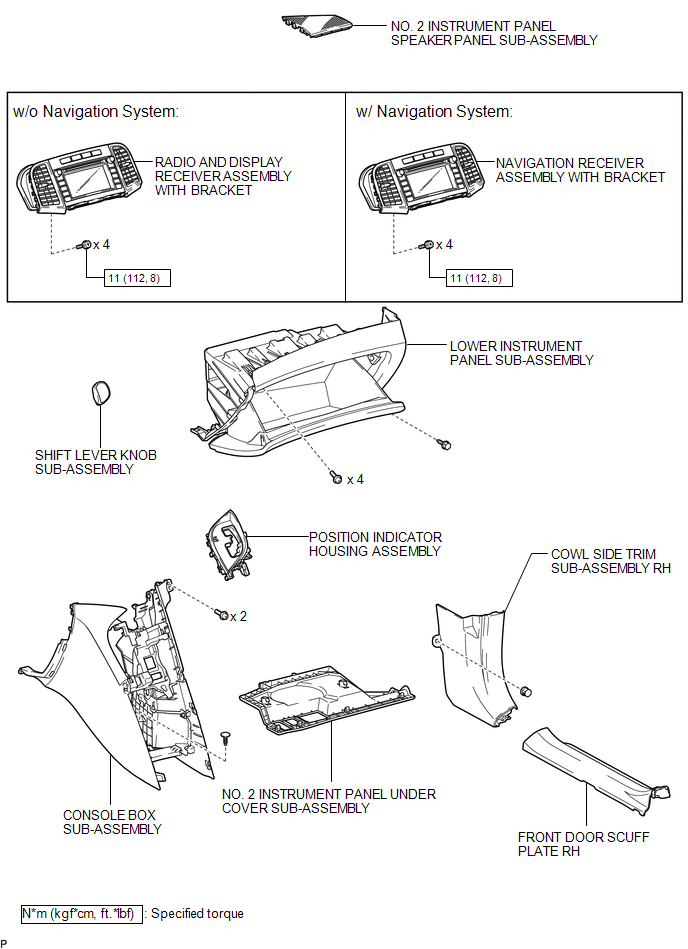
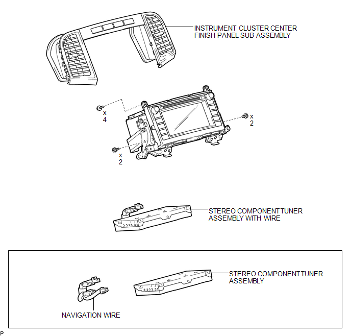
COMPONENTS
ILLUSTRATION
.png)
ILLUSTRATION
ILLUSTRATION

 Removal
REMOVAL
PROCEDURE
1. PRECAUTION (w/ Navigation System)
NOTICE:
After turning the ignition switch off, waiting time may be required before disconnecting
the cable from the negative (-) battery te ...
Other materials about Toyota Venza:
Reassembly
REASSEMBLY
PROCEDURE
1. INSTALL GENERATOR ROTOR ASSEMBLY
(a) Place the generator drive end frame on the generator pulley.
(b) Install the generator rotor to the generator drive end frame.
...
On-vehicle Inspection
ON-VEHICLE INSPECTION
CAUTION / NOTICE / HINT
CAUTION:
Be sure to follow the correct removal and installation procedures of the steering
pad.
PROCEDURE
1. INSPECT STEERING PAD (Vehicle not Involved in Collision)
(a) Perform a diagnostic system check (S ...
On-vehicle Inspection
ON-VEHICLE INSPECTION
CAUTION / NOTICE / HINT
CAUTION:
Be sure to follow the correct removal and installation procedures of the front
seat side airbag assembly.
PROCEDURE
1. INSPECT FRONT SEAT SIDE AIRBAG ASSEMBLY (VEHICLE NOT INVOLVED IN COLLISION)
(a ...

0.1417