Toyota Venza: Components
COMPONENTS
ILLUSTRATION
ILLUSTRATION
.png)
ILLUSTRATION
ILLUSTRATION

 Removal
REMOVAL
PROCEDURE
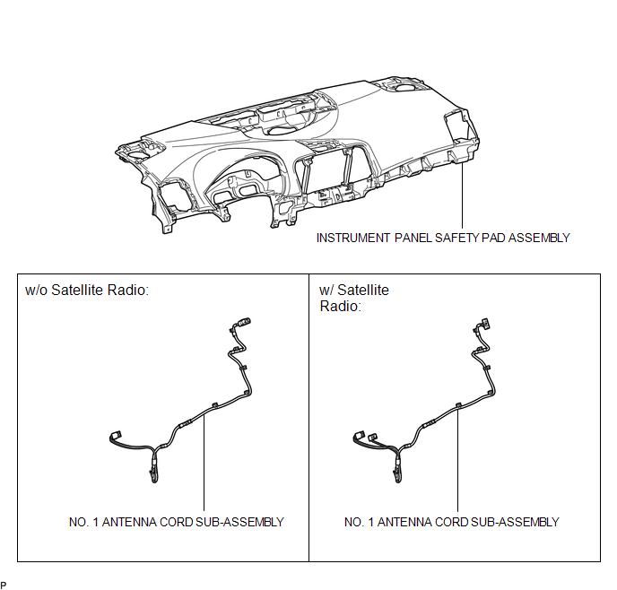
1. REMOVE INSTRUMENT PANEL SAFETY PAD ASSEMBLY
(See page )
2. REMOVE NO. 1 ANTENNA CORD SUB-ASSEMBLY
(a) Disengage the 7 clamps and remove the No. 1 antenna cord sub-assembly.
...
Other materials about Toyota Venza:
Torque Converter And Drive Plate
Inspection
INSPECTION
PROCEDURE
1. INSPECT TORQUE CONVERTER ASSEMBLY
(a) Inspect the one-way clutch.
(1) Press on the serrations of the stator with a finger and rotate it.
Check that it rotates smoothly when turned clockwise and locks whe ...
Test Mode Procedure
TEST MODE PROCEDURE
1. ENTER TEST MODE (SIGNAL CHECK MODE)
(a) Turn the ignition switch off.
(b) Connect the Techstream to the DLC3.
(c) Turn the ignition switch to ON.
(d) Check that the tire pressure warning light comes on for 3 seconds and then
goes ...
Installation
INSTALLATION
PROCEDURE
1. INSTALL HEADLIGHT ASSEMBLY
(a) Connect each connector.
(b) Install the headlight assembly with the bolt and 3 screws.
Torque:
3.6 N·m {37 kgf·cm, 32 in·lbf}
2. INSTALL FRONT BUMPER ASSEMBLY
(See page )
3. CONNECT CABLE T ...

0.1223