Toyota Venza: Components
COMPONENTS
ILLUSTRATION
ILLUSTRATION
ILLUSTRATION
ILLUSTRATION
 Luggage Speaker
...
 Removal
REMOVAL
PROCEDURE
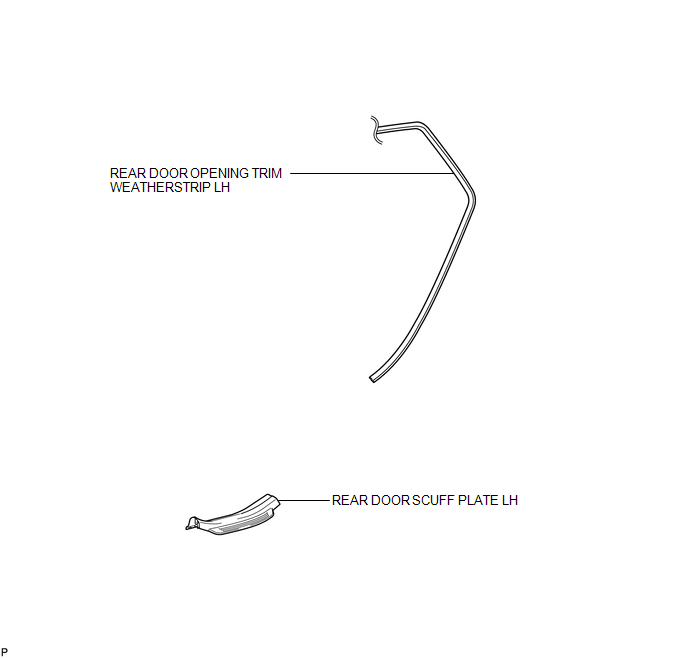
1. REMOVE REAR DOOR SCUFF PLATE LH
2. REMOVE REAR DOOR OPENING TRIM WEATHERSTRIP LH
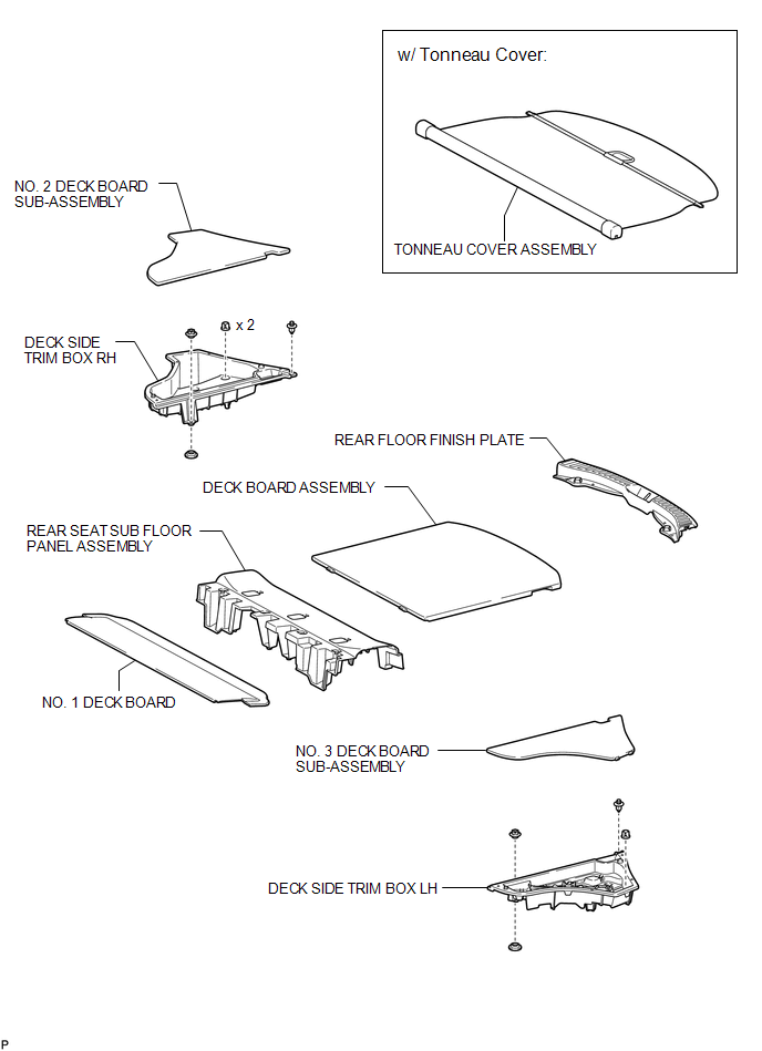
3. REMOVE TONNEAU COVER ASSEMBLY (w/ Tonneau Cover)
4. REMOVE DECK BOARD ASSEMBLY
...
Other materials about Toyota Venza:
Reassembly
REASSEMBLY
PROCEDURE
1. INSTALL NO. 3 ANTENNA CORD SUB-ASSEMBLY
2. INSTALL ROOF HEADLINING ASSEMBLY
HINT:
Refer to the procedure from Install Roof Headlining Assembly (See page
).
3. INSTALL REAR WIPER MOTOR AND BRACKET ASSEMBLY
4. INSTALL REAR ...
Inspection
INSPECTION
PROCEDURE
1. INSPECT CHARCOAL CANISTER ASSEMBLY
(a) Visually check the charcoal canister assembly.
(1) Visually check the charcoal canister assembly for cracks or damage.
If cracks or damage are found, replace the charcoal canister ...
Electrical Key Oscillator(for Rear Floor)
Components
COMPONENTS
ILLUSTRATION
Removal
REMOVAL
PROCEDURE
1. REMOVE TONNEAU COVER ASSEMBLY (w/ Tonneau Cover)
2. REMOVE DECK BOARD ASSEMBLY
3. REMOVE NO. 3 DECK BOARD SUB-ASSEMBLY
4. REMOVE DECK SIDE TRIM BOX LH
5. REMOVE NO. 2 D ...

0.1568