Toyota Venza: Installation
INSTALLATION
PROCEDURE
1. INSTALL INSTRUMENT PANEL WIRE ASSEMBLY
|
(a) Connect the vent hole connector of the instrument panel wire to the front passenger airbag assembly. Text in Illustration
NOTICE: When connecting any airbag connector, take care not to damage the airbag wire harness. |
|
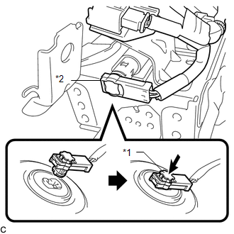
(b) Push in the vent hole connector lock to install the vent hole connector.
|
(c) Connect the 2 airbag connectors of the instrument panel wire to the front passenger airbag assembly. Text in Illustration
NOTICE:
|
|
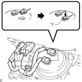
(d) Push in the 2 airbag connector locks to install the 2 airbag connectors.
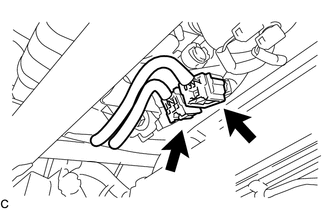
(e) Engage the 2 clamps.
2. INSTALL FRONT PASSENGER AIRBAG ASSEMBLY
(a) Engage the 5 hooks.
(b) Push in the front passenger airbag assembly to engage the 5 hooks.
(c) Install the 2 screws to install the front passenger airbag assembly.
3. INSTALL INSTRUMENT PANEL SAFETY PAD ASSEMBLY
.gif)
4. CONNECT INSTRUMENT PANEL WIRE ASSEMBLY
(a) Check that the ignition switch is off.
(b) Check that the cable is disconnected from the negative (-) battery terminal.
CAUTION:
Wait at least 90 seconds after disconnecting the cable from the negative (-) battery terminal to disable the SRS system.
|
(c) Connect the 2 connectors. NOTICE: When connecting the airbag connector, take care not to damage the airbag wire harness. |
|
5. INSTALL SHIFT LEVER ASSEMBLY
(See page )
6. PERFORM DIAGNOSTIC SYSTEM CHECK
(See page )
7. INSPECT SRS WARNING LIGHT
(See page )
 Removal
REMOVAL
PROCEDURE
1. PRECAUTION
NOTICE:
Be sure to read Precaution thoroughly before servicing (See page
).
2. REMOVE SHIFT LEVER ASSEMBLY
(See page )
3. DISCONNECT INSTRUMENT PANEL WIRE ASS ...
 Disposal
DISPOSAL
CAUTION / NOTICE / HINT
CAUTION:
Before performing pre-disposal deployment of any SRS component, review and closely
follow all applicable environmental and hazardous material regulations ...
Other materials about Toyota Venza:
Installation
INSTALLATION
CAUTION / NOTICE / HINT
HINT:
Use the same procedure for the RH side and LH side.
The procedure listed below is for the LH side.
PROCEDURE
1. INSTALL REAR AXLE CARRIER SUB-ASSEMBLY
(a) Temporarily install the rea ...
Installation
INSTALLATION
PROCEDURE
1. INSTALL ROOF HEADLINING ASSEMBLY (w/o Sliding Roof)
(a) Pull the roof headlining assembly into the vehicle through the back
door.
NOTICE:
Do not damage the roof headlining assembly or body interior.
...
Glass Position Initialization Incomplete (B2313)
DESCRIPTION
The power window regulator motor assembly is operated by the power window regulator
master switch assembly or power window regulator switch assembly. The power window
regulator motor assembly has motor, regulator and ECU functions.
When the E ...

0.1607