
Toyota Venza: Components
COMPONENTS
ILLUSTRATION
.png)
ILLUSTRATION
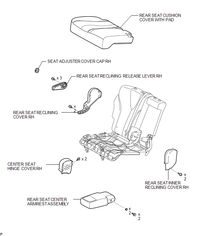
ILLUSTRATION
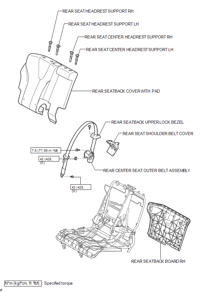

 Removal
REMOVAL
PROCEDURE
1. REMOVE REAR SEAT HEADREST ASSEMBLY
2. REMOVE REAR SEAT CENTER HEADREST ASSEMBLY
3. REMOVE REAR SEAT INNER TRACK BRACKET COVER
4. REMOVE REAR SEAT OUTER TRACK BRACKET ...
Other materials about Toyota Venza:
Disassembly
DISASSEMBLY
PROCEDURE
1. REMOVE TAIL AND STOP LIGHT BULB
(a) Turn the tail and stop light bulb and the rear combination light
socket and wire in the direction indicated by the arrow shown in the illustration,
and remove them as a unit.
...
Inspection
INSPECTION
PROCEDURE
1. INSPECT NO. 1 VALVE ROCKER ARM SUB-ASSEMBLY
(a) Turn the roller by hand to check that it turns smoothly.
If the roller does not turn smoothly, replace the No. 1 valve rocker
arm sub-assembly.
...
System Description
SYSTEM DESCRIPTION
1. DESCRIPTION
(a) The steering lock system locks/unlocks the steering when by activating the
steering lock bar with a motor. The steering lock ECU (steering lock actuator assembly)
activates the motor based on signals from the certifi ...

0.1331