Toyota Venza: Removal
REMOVAL
PROCEDURE
1. RECOVER REFRIGERANT FROM REFRIGERATION SYSTEM
.gif)
2. DISCONNECT CABLE FROM NEGATIVE BATTERY TERMINAL
NOTICE:
When disconnecting the cable, some systems need to be initialized after the cable
is reconnected (See page ).
3. REMOVE FRONT WHEEL RH
4. REMOVE NO. 1 ENGINE UNDER COVER
5. REMOVE NO. 2 ENGINE UNDER COVER
6. SEPARATE FRONT FENDER LINER RH
7. REMOVE FRONT FENDER APRON RH
8. REMOVE V-RIBBED BELT
9. DRAIN ENGINE COOLANT
10. REMOVE V-BANK COVER SUB-ASSEMBLY
11. REMOVE COOL AIR INTAKE DUCT SEAL
12. REMOVE RADIATOR GRILLE
13. REMOVE INLET NO. 2 AIR CLEANER
14. REMOVE AIR CLEANER CAP WITH HOSE
15. REMOVE AIR CLEANER CASE
16. REMOVE BATTERY
17. REMOVE INLET NO. 1 AIR CLEANER
18. REMOVE LOW PITCHED HORN ASSEMBLY
19. REMOVE HIGH PITCHED HORN ASSEMBLY
20. REMOVE HOOD LOCK ASSEMBLY (w/o Engine Hood Courtesy Switch)
21. REMOVE HOOD LOCK ASSEMBLY (w/ Engine Hood Courtesy Switch)
22. REMOVE HOOD LOCK SUPPORT SUB-ASSEMBLY
23. DISCONNECT OUTLET RESERVE TANK HOSE
24. DISCONNECT NO. 1 RADIATOR HOSE
25. REMOVE NO. 2 RADIATOR HOSE
26. DISCONNECT INLET OIL COOLER HOSE
27. DISCONNECT OUTLET OIL COOLER HOSE
28. REMOVE UPPER RADIATOR SUPPORT
29. DISCONNECT COOLER REFRIGERANT DISCHARGE HOSE
30. DISCONNECT AIR CONDITIONING TUBE AND ACCESSORY ASSEMBLY
31. REMOVE COOLER CONDENSER ASSEMBLY
32. REMOVE RADIATOR ASSEMBLY AND FAN ASSEMBLY WITH MOTOR
33. DISCONNECT COOLER REFRIGERANT DISCHARGE HOSE
|
(a) Remove the bolt and disconnect the cooler refrigerant discharge hose from the compressor and magnetic clutch. |
|
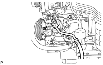
(b) Remove the O-ring from the discharge hose.
NOTICE:
Seal the openings of the disconnected parts using vinyl tape to prevent entry of moisture and foreign matter.
34. DISCONNECT SUCTION HOSE SUB-ASSEMBLY
|
(a) Remove the bolt and disconnect the suction hose sub-assembly from the compressor and magnetic clutch. |
|
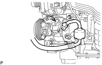
(b) Remove the O-ring from the suction hose sub-assembly.
NOTICE:
Seal the openings of the disconnected parts using vinyl tape to prevent entry of moisture and foreign matter.
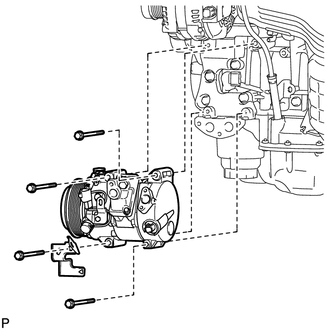
35. REMOVE COMPRESSOR AND MAGNETIC CLUTCH
|
(a) Disengage each clamp. |
|
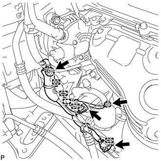
(b) Disconnect each connector.
|
(c) Remove the 4 bolts, bracket, and the compressor and magnetic clutch. |
|
 Components
COMPONENTS
ILLUSTRATION
ILLUSTRATION
ILLUSTRATION
ILLUSTRATION
ILLUSTRATION
...
 Disassembly
DISASSEMBLY
PROCEDURE
1. REMOVE MAGNETIC CLUTCH ASSEMBLY
(a) Place the compressor and magnetic clutch in a vise.
(b) Using SST, hold the m ...
Other materials about Toyota Venza:
Disassembly
DISASSEMBLY
CAUTION / NOTICE / HINT
NOTICE:
When disassembling the multiplex network door ECU, eliminate static electricity
by touching the vehicle body to prevent the components from being damaged.
PROCEDURE
1. REMOVE MULTIPLEX NETWORK DOOR ECU
...
Data List / Active Test
DATA LIST / ACTIVE TEST
1. DATA LIST
Using the Techstream to read the Data List allows the values or states of switches,
sensors, actuators and other items to be read without removing any parts. This non-intrusive
inspection can be very useful because in ...
Problem Symptoms Table
PROBLEM SYMPTOMS TABLE
Use the table below to help determine the cause of problem symptoms. If multiple
suspected areas are listed, the potential causes of the symptoms are listed in order
of probability in the "Suspected Area" column of the tab ...

0.1673