Toyota Venza: Components
COMPONENTS
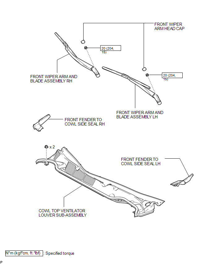
ILLUSTRATION
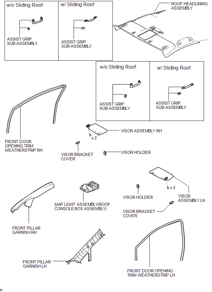
ILLUSTRATION
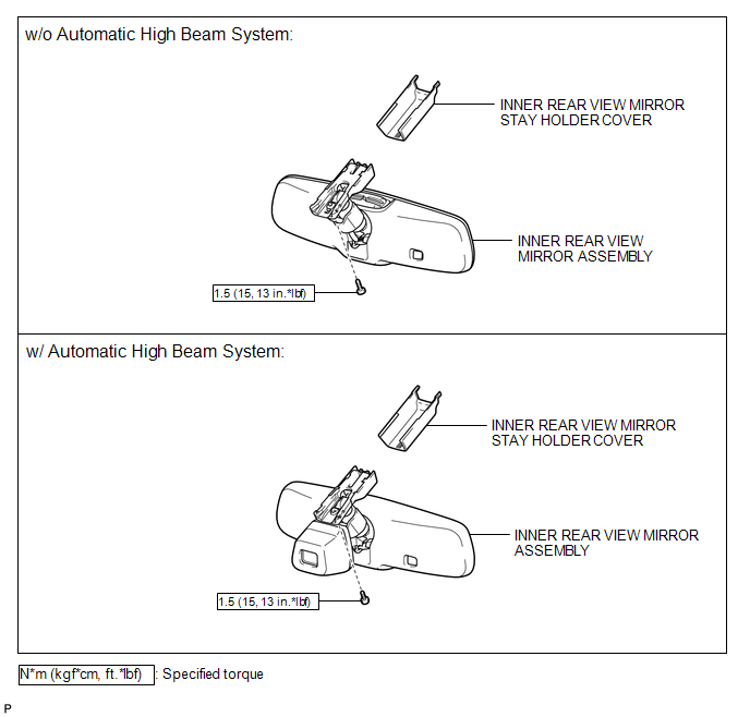
ILLUSTRATION
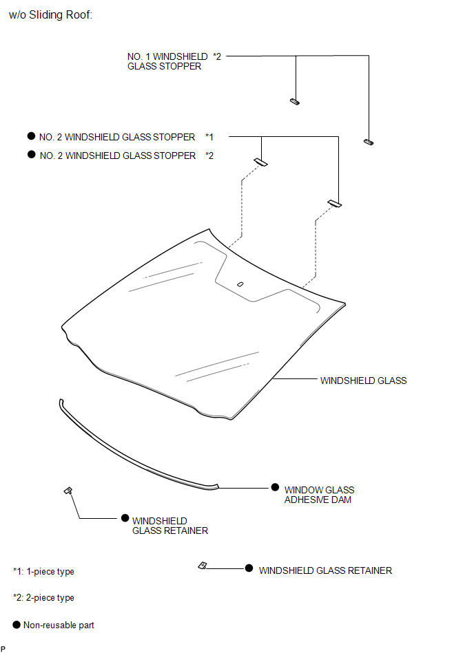
ILLUSTRATION
ILLUSTRATION
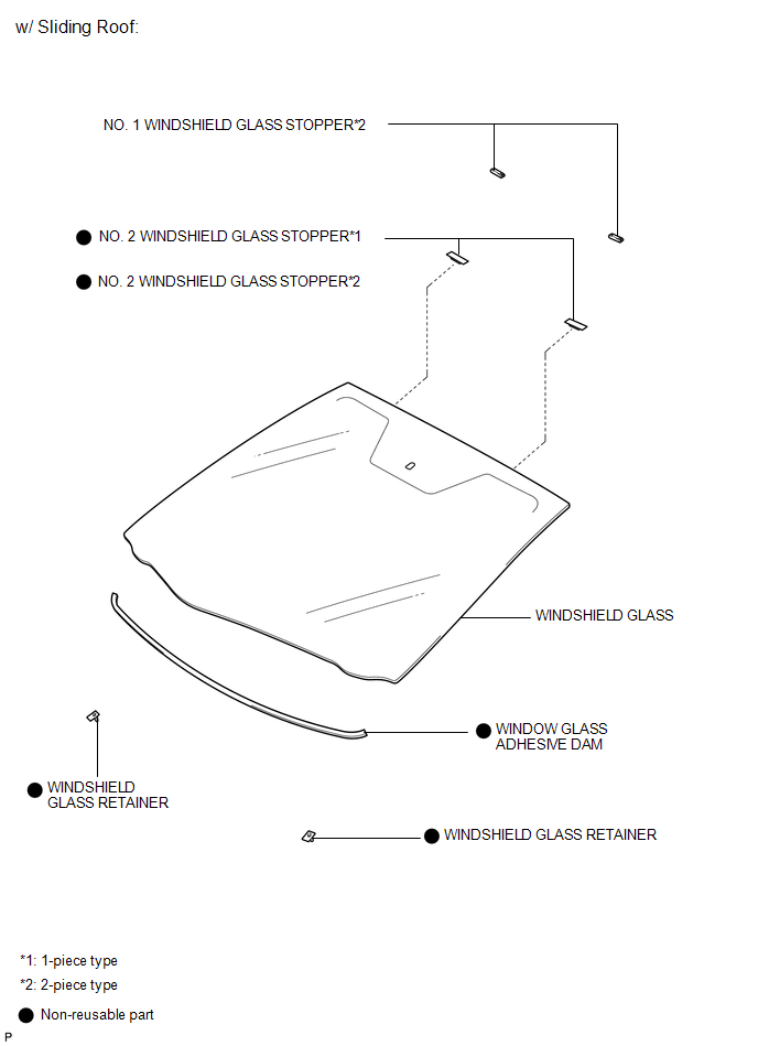
 Windshield Glass
...
 Removal
REMOVAL
CAUTION / NOTICE / HINT
NOTICE:
w/Camera mirror:The timing of the change between high beams and low beams differs
depending on the light transmission rate of the glass. For this reason, w ...
Other materials about Toyota Venza:
System Description
SYSTEM DESCRIPTION
1. POWER DOOR LOCK CONTROL SYSTEM DESCRIPTION
(a) The power door lock system locks/unlocks all doors.
The door control switch sends "lock/unlock" request signals to the main body
ECU (driver side junction block assembly). Then ...
System Diagram
SYSTEM DIAGRAM
Communication Table
Sender
Receiver
Signal
Line
Main Body ECU
(Driver Side Junction Block Assembly)
Clearance Warning ECU Assembly
Destination information
...
Installation
INSTALLATION
PROCEDURE
1. INSTALL REAR SEAT ASSEMBLY LH
(a) Place the rear seat assembly LH in the cabin.
NOTICE:
Be careful not to damage the vehicle body.
(b) Temporarily install the 2 bolts on the front side of the seat.
...

0.1148