Toyota Venza: Removal
REMOVAL
CAUTION / NOTICE / HINT
HINT:
When installing new name plates and emblem, heat the vehicle body, name plates and emblem using a heat light.
Heating Temperature|
Item |
Temperature |
|---|---|
|
Vehicle Body |
40 to 60°C (104 to 140°F) |
|
Emblem, Name Plate |
20 to 30°C (68 to 86°F) |
NOTICE:
Do not heat the vehicle body, name plates or emblem excessively.
PROCEDURE
1. REMOVE HOOD EMBLEM
|
(a) Put protective tape around the hood emblem. Text in Illustration
|
|
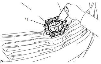
(b) Using a moulding remover, peel off the double-sided tape to remove the hood emblem.
NOTICE:
- If reusing the emblem, take care not to damage the hood emblem.
- Be careful not to damage the vehicle body.
2. REMOVE NO. 1 BACK DOOR EMBLEM
|
(a) Put protective tape around the No. 1 back door emblem. Text in Illustration
|
|
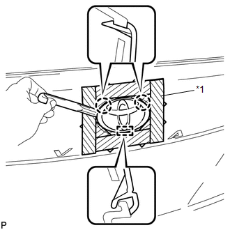
(b) Using a moulding remover, disengage the 2 claws.
NOTICE:
- If reusing the emblem, take care not to damage the No. 1 back door emblem.
- Be careful not to damage the vehicle body.
(c) Disengage the guide and remove the No. 1 back door emblem.
3. REMOVE NO. 2 BACK DOOR NAME PLATE
|
(a) Put protective tape around the No. 2 back door name plate. Text in Illustration
|
|
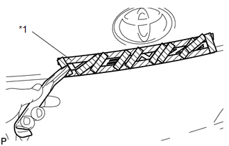
(b) Using a moulding remover, peel off the double-sided tape to remove the No. 2 back door name plate.
NOTICE:
- If reusing the name plate, take care not to damage the No. 2 back door name plate.
- Be careful not to damage the vehicle body.
4. REMOVE NO. 3 BACK DOOR NAME PLATE (for AWD)
|
(a) Put protective tape around the No. 3 back door name plate. Text in Illustration
|
|
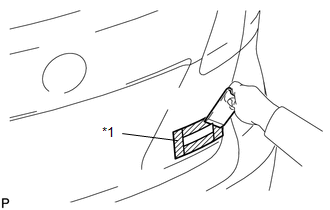
(b) Using a moulding remover, peel off the double-sided tape to remove the No. 3 back door name plate.
NOTICE:
- If reusing the name plate, take care not to damage the No. 3 back door name plate.
- Be careful not to damage the vehicle body.
5. REMOVE NO. 4 LUGGAGE COMPARTMENT DOOR PLATE (w/ Grade Mark)
|
(a) Put protective tape around the No. 4 luggage compartment door plate. Text in Illustration
|
|
(b) Using a moulding remover, peel off the double-sided tape to remove the No. 4 luggage compartment door plate.
NOTICE:
- If reusing the door plate, take care not to damage the No. 4 luggage compartment door plate.
- Be careful not to damage the vehicle body.
 Components
COMPONENTS
ILLUSTRATION
...
 Installation
INSTALLATION
CAUTION / NOTICE / HINT
HINT:
When installing new name plates and emblem, heat the vehicle body, name plates
and emblem using a heat light.
Heating Temperature
Item
...
Other materials about Toyota Venza:
Fail-safe Chart
FAIL-SAFE CHART
If any of the following DTCs are stored, the ECM enters fail-safe mode to allow
the vehicle to be driven temporarily or stops fuel injection.
DTC Code
Component
Fail-Safe Operation
Fail-Safe Deact ...
Diagnosis System
DIAGNOSIS SYSTEM
1. DESCRIPTION
(a) The power window control system data can be read from the Data Link Connector
3 (DLC3) of the vehicle. When the system seems to be malfunctioning, use the Techstream
to check for malfunctions and perform repairs.
2. C ...
Problem Symptoms Table
PROBLEM SYMPTOMS TABLE
HINT:
Use the table below to help determine the cause of problem symptoms.
If multiple suspected areas are listed, the potential causes of the symptoms
are listed in order of probability in the "Suspected Area" ...

0.1301