Toyota Venza: Components
COMPONENTS
ILLUSTRATION
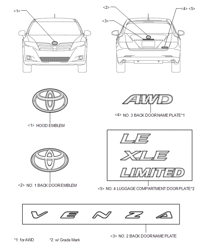
 Name Plate
...
 Removal
REMOVAL
CAUTION / NOTICE / HINT
HINT:
When installing new name plates and emblem, heat the vehicle body, name plates
and emblem using a heat light.
Heating Temperature
Item
...
Other materials about Toyota Venza:
Pressure Control Solenoid "C" Electrical (Shift Solenoid Valve SL3) (P0798)
DESCRIPTION
Changing from 1st to 6th is performed by the TCM turning shift solenoid valves
SL1, SL2, SL3, SL4 and SL on and off. If an open or short circuit occurs in any
of the shift solenoid valves, the TCM controls the remaining normal shift solenoid
...
ECM / PCM Processor (P0606)
MONITOR DESCRIPTION
The ECM continuously monitors its main and sub CPUs. This self-check ensures
that the ECM is functioning properly. If outputs from the CPUs are different and
deviate from the standard, the ECM illuminates the MIL and stores the DTC imm ...
Freeze Frame Data
FREEZE FRAME DATA
1. FREEZE FRAME DATA
(a) Whenever a DTC is detected, the AFS ECU (headlight swivel ECU assembly) stores
the current vehicle (sensor) state as Freeze Frame Data.
2. CHECK FREEZE FRAME DATA
(a) Connect the Techstream to the DLC3.
(b) Tur ...

0.1383