Toyota Venza: Removal
REMOVAL
PROCEDURE
1. DISCONNECT CABLE FROM NEGATIVE BATTERY TERMINAL
CAUTION:
Wait at least 90 seconds after disconnecting the cable from the negative (-) battery terminal to disable the SRS system.
NOTICE:
When disconnecting the cable, some systems need to be initialized after the cable
is reconnected (See page .gif) ).
).
2. REMOVE FRONT DOOR INSIDE HANDLE BEZEL PLUG
3. REMOVE POWER WINDOW REGULATOR MASTER SWITCH ASSEMBLY WITH FRONT DOOR ARMREST BASE PANEL (for Driver Side)
4. REMOVE POWER WINDOW REGULATOR SWITCH ASSEMBLY WITH FRONT DOOR ARMREST BASE PANEL (for Front Passenger Side)
5. REMOVE COURTESY LIGHT ASSEMBLY
6. REMOVE FRONT DOOR TRIM BOARD SUB-ASSEMBLY
7. REMOVE FRONT DOOR INSIDE HANDLE SUB-ASSEMBLY
8. REMOVE DOOR SIDE AIRBAG SENSOR
9. REMOVE FRONT NO. 1 SPEAKER ASSEMBLY
10. REMOVE FRONT DOOR SERVICE HOLE COVER
11. REMOVE FRONT DOOR GLASS SUB-ASSEMBLY
12. REMOVE FRONT DOOR GLASS RUN
13. REMOVE FRONT DOOR BELT MOULDING
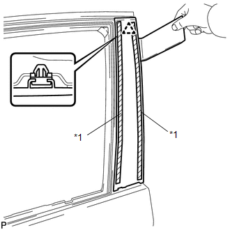
14. DISCONNECT FRONT DOOR WEATHERSTRIP
|
(a) Using a clip remover, disengage the 2 clips and remove the upper part of the front door weatherstrip to the extent that allows removal of the front door window frame moulding. |
|
.png)
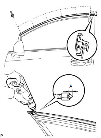
15. REMOVE FRONT DOOR REAR WINDOW FRAME MOULDING
HINT:
When removing the front door rear window frame moulding, heat the vehicle body and front door rear window frame moulding using a heat light.
Heating Temperature|
Item |
Temperature |
|---|---|
|
Vehicle Body |
40 to 60°C (104 to 140°F) |
|
Moulding |
20 to 30°C (68 to 86°F) |
NOTICE:
Do not heat the vehicle body or moulding excessively.
(a) Using a heat light, heat the front door rear window frame moulding.
|
(b) Using a moulding remover, remove the clip and front door rear window frame moulding. Text in Illustration
|
|
16. REMOVE FRONT DOOR SCUFF PLATE
17. REMOVE COWL SIDE TRIM SUB-ASSEMBLY
18. REMOVE FRONT DOOR PANEL SUB-ASSEMBLY
(a) Disconnect each connector.
|
(b) Remove the bolt <A> and disengage the front door check assembly. |
|
.png)
(c) Remove the 4 bolts <B> and front door panel sub-assembly.
NOTICE:
To prevent damage, when removing the front door panel sub-assembly, make sure that there are enough people available to hold it securely.
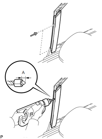
19. REMOVE FRONT DOOR UPPER WINDOW FRAME MOULDING
(a) Insert a 4.0 mm (0.157 in.) drill bit into a drill.
|
(b) Tape the 4.0 mm (0.157 in.) drill bit 5.0 mm (0.197 in.) from the tip as shown in the illustration.
NOTICE: Tape the 4.0 mm (0.157 in.) drill bit to prevent the drill bit from going too deep. |
|
(c) Lightly press the drill against the rivets to drill off the rivet flanges, and remove the 6 rivets.
NOTICE:
- Pressing the drill too firmly will cause the rivet to turn and result in the rivet not being drilled through.
- Prying the rivets with the drill may damage the rivet installation holes or drill bit.
- Be careful of the drilled rivets, as they may be hot.
(d) Using a vacuum cleaner, remove the rivet fragments and shavings from the drilled areas.
(e) Disengage the guide and remove the front door upper window frame moulding from the door frame.
20. REMOVE FRONT DOOR FRONT WINDOW FRAME MOULDING
(a) Insert a 4.0 mm (0.157 in.) drill bit into a drill.
|
(b) Tape the 4.0 mm (0.157 in.) drill bit 5.0 mm (0.197 in.) from the tip as shown in the illustration.
NOTICE: Tape the 4.0 mm (0.157 in.) drill bit to prevent the drill bit from going too deep. |
|
(c) Lightly press the drill against the rivets to drill off the rivet flanges, and remove the 2 rivets.
NOTICE:
- Pressing the drill too firmly will cause the rivet to turn and result in the rivet not being drilled through.
- Prying the rivets with the drill may damage the rivet installation holes or drill bit.
- Be careful of the drilled rivets, as they may be hot.
(d) Using a vacuum cleaner, remove the rivet fragments and shavings from the drilled areas.
(e) Disengage the guide and remove the front door front window frame moulding from the door frame.
 Installation
INSTALLATION
PROCEDURE
1. INSTALL FRONT DOOR FRONT WINDOW FRAME MOULDING
(a) Engage the front door front window frame moulding to the door frame.
...
 Name Plate
...
Other materials about Toyota Venza:
Installation
INSTALLATION
PROCEDURE
1. INSTALL REAR SEAT OUTER BELT ASSEMBLY
(a) Engage the 2 guides.
(b) Install the rear seat outer belt assembly with the 2 bolts.
Torque:
Bolt <A> :
7.5 N·m {77 kg ...
Operation Check
OPERATION CHECK
1. CHECK REMOTE CONTROL MIRROR FUNCTION
(a) Turn the ignition switch ON.
(b) With the mirror select switch set to L, check that the outer rear view mirror
LH surface moves up, down, left and right normally.
(c) With the mirror select swit ...
Precaution
PRECAUTION
1. PRECAUTION FOR DISCONNECTING CABLE FROM NEGATIVE BATTERY TERMINAL
NOTICE:
After the ignition switch is turned off, the navigation receiver assembly
records various types of memory and settings. As a result, after turning
the ig ...

0.1785