Toyota Venza: All Doors LOCK/UNLOCK Functions do not Operate Via Door Control Switch
DESCRIPTION
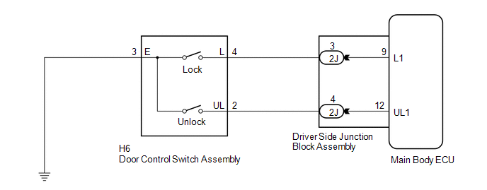
The main body ECU (driver side junction block assembly) receives switch signals from the door control switch and activates the door lock motor on each door according to these signals.
WIRING DIAGRAM
PROCEDURE
|
1. |
READ VALUE USING TECHSTREAM (DOOR CONTROL SWITCH) |
(a) Connect the Techstream to the DLC3.
(b) Turn the ignition switch to ON.
(c) Turn the Techstream on.
(d) Enter the following menus: Body Electrical / Main Body / Data List.
(e) Read the Data List according to the display on the Techstream.
Main Body (Main Body ECU (Driver Side Junction Block Assembly))|
Tester Display |
Measurement Item/Range |
Normal Condition |
Diagnostic Note |
|---|---|---|---|
|
Door Lock SW-Lock |
Front passenger side door control switch lock signal/ON or OFF |
ON: Front passenger side door control switch pushed to lock position OFF: Front passenger side door control switch not pushed to lock position |
- |
|
Door Lock SW-Unlock |
Front passenger side door control switch unlock signal/ON or OFF |
ON: Front passenger side door control switch pushed to unlock position OFF: Front passenger side door control switch not pushed to unlock position |
- |
OK:
On the Techstream screen, ON or OFF will be displayed accordingly.
| OK | .gif) |
REPLACE MAIN BODY ECU (DRIVER SIDE JUNCTION BLOCK ASSEMBLY) |
|
.gif)
|
2. |
INSPECT DOOR CONTROL SWITCH ASSEMBLY |
|
(a) Remove the door control switch assembly (See page
|
|
.gif) ).
)..png)
(b) Measure the resistance according to the value(s) in the table below.
Standard Resistance:
|
Tester Connection |
Condition |
Specified Condition |
|---|---|---|
|
4 (L) - 3 (E) |
Lock |
Below 1 Ω |
|
4 (L) - 3 (E) |
Off |
10 kΩ or higher |
|
2 (UL) - 3 (E) |
Unlock |
Below 1 Ω |
|
2 (UL) - 3 (E) |
Off |
10 kΩ or higher |
|
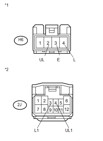
*1 |
Component without harness connected (Door Control Switch Assembly) |
|
*2 |
Unlock |
|
*3 |
Lock |
| NG | |
REPLACE DOOR CONTROL SWITCH ASSEMBLY |
|
|
3. |
CHECK HARNESS AND CONNECTOR (DOOR CONTROL SWITCH - MAIN BODY ECU AND BODY GROUND) |
|
(a) Disconnect the 2J driver side junction block connector. |
|
(b) Measure the resistance according to the value(s) in the table below.
Standard Resistance:
|
Tester Connection |
Condition |
Specified Condition |
|---|---|---|
|
H6-2 (UL) - 2J-4 (UL1) |
Always |
Below 1 Ω |
|
H6-4 (L) - 2J-3 (L1) |
Always |
Below 1 Ω |
|
H6-3 (E) - Body ground |
Always |
Below 1 Ω |
|
H6-2 (UL) - Body ground |
Always |
10 kΩ or higher |
|
H6-4 (L) - Body ground |
Always |
10 kΩ or higher |
|
*1 |
Front view of wire harness connector (to Door Control Switch Assembly) |
|
*2 |
Front view of wire harness connector (to Main Body ECU (Driver Side Junction Block Assembly)) |
| OK | |
REPLACE MAIN BODY ECU (DRIVER SIDE JUNCTION BLOCK ASSEMBLY) |
| NG | |
REPAIR OR REPLACE HARNESS OR CONNECTOR |
 Data List / Active Test
DATA LIST / ACTIVE TEST
1. DATA LIST
HINT:
Using the Techstream to read the Data List allows the values or states of switches,
sensors, actuators and other items to be read without removing any p ...
 Rear Door Lock
...
Other materials about Toyota Venza:
Door Courtesy Switch Circuit
DESCRIPTION
When an additional transponder key is registered, the transponder key ECU assembly
detects the front door courtesy light switch assembly (for driver side) open/close
condition, and enters the key registration mode.
WIRING DIAGRAM
CAUTION / ...
Inspection
INSPECTION
PROCEDURE
1. INSPECT THERMOSTAT
HINT:
The valve opening temperature is inscribed on the thermostat.
(a) Immerse the thermostat in water, and then gradually heat the water.
(b) Check t ...
On-vehicle Inspection
ON-VEHICLE INSPECTION
CAUTION / NOTICE / HINT
CAUTION:
Be sure to follow the correct removal and installation procedures of the front
airbag sensor.
PROCEDURE
1. INSPECT FRONT AIRBAG SENSOR (VEHICLE NOT INVOLVED IN COLLISION)
(a) Perform a diagnostic s ...

0.115