Toyota Venza: Disassembly
DISASSEMBLY
PROCEDURE
1. REMOVE NO. 1 ULTRASONIC SENSOR (w/ Intuitive Parking Assist System)
.gif)
2. REMOVE NO. 2 ULTRASONIC SENSOR RETAINER (w/ Intuitive Parking Assist System)
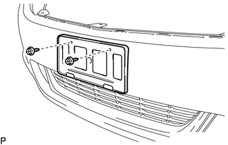
3. REMOVE FRONT LICENSE PLATE BRACKET
|
(a) Remove the 2 screws and front license plate bracket. |
|
4. REMOVE FOG LIGHT ASSEMBLY LH
5. REMOVE FOG LIGHT ASSEMBLY RH
HINT:
Use the same procedure for the RH side and LH side.
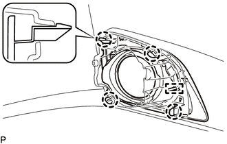
6. REMOVE FRONT BUMPER HOLE COVER ASSEMBLY LH
|
(a) Disengage the 4 claws and pin, and remove the front bumper hole cover assembly LH. |
|
7. REMOVE FRONT BUMPER HOLE COVER ASSEMBLY RH
HINT:
Use the same procedure for the RH side and LH side.
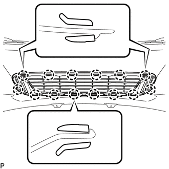
8. REMOVE NO. 1 LOWER RADIATOR GRILLE
|
(a) Disengage the 14 claws and remove the No. 1 lower radiator grille. |
|
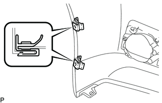
9. REMOVE FRONT BUMPER MOULDING
|
(a) Remove the 2 screws. |
|
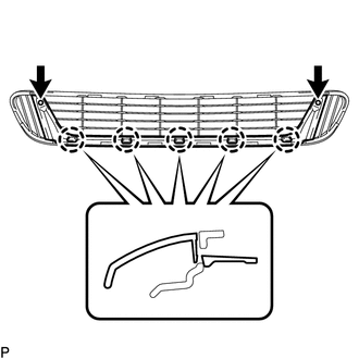
(b) Disengage the 5 claws and remove the front bumper moulding.
10. REMOVE FRONT FENDER LINER RETAINER
|
(a) Remove the 2 front fender liner retainers. HINT: Use the same procedure for the RH side and LH side. |
|
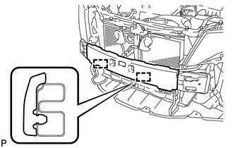
11. REMOVE FRONT BUMPER ENERGY ABSORBER
|
(a) Disengage the 2 guides and remove the front bumper energy absorber. |
|
12. REMOVE FRONT BUMPER REINFORCEMENT SUB-ASSEMBLY
|
(a) Disengage the 4 clamps. |
|
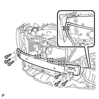
(b) Remove the 6 bolts and front bumper reinforcement sub-assembly.
13. REMOVE FRONT BUMPER SIDE RETAINER LH
|
(a) Remove the bolt and screw. Text in Illustration
|
|
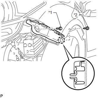
(b) Disengage the claw and remove the front bumper side retainer LH.
14. REMOVE FRONT BUMPER SIDE RETAINER RH
HINT:
Use the same procedure for the RH side and LH side.
 Removal
REMOVAL
PROCEDURE
1. REMOVE COOL AIR INTAKE DUCT SEAL
(a) Using a clip remover, remove the 12 clips and cool air intake duct
seal.
2. ...
 Reassembly
REASSEMBLY
PROCEDURE
1. INSTALL FRONT BUMPER SIDE RETAINER LH
(a) Engage the claw and install the front bumper side retainer LH.
Text in Illustration
*1
...
Other materials about Toyota Venza:
Removal
REMOVAL
CAUTION / NOTICE / HINT
HINT:
Use the same procedure for the RH side and LH side.
The procedure listed below is for the LH side.
PROCEDURE
1. REMOVE REAR WHEEL
2. REMOVE DECK SIDE TRIM
(a) Disengage the 5 claws, and ...
Installation
INSTALLATION
PROCEDURE
1. INSTALL POWER STEERING ECU ASSEMBLY
(a) Engage the 4 wire harness clamps to the power steering ECU assembly.
(b) Install the power steering ECU assembly with the ...
Fail-safe Chart
FAIL-SAFE CHART
If a problem occurs in the power steering system, the power steering assist will
be stopped or the amount of power assist will be decreased to protect the system.
Power Steering System
Malfunction
Fail-safe Operation
...

0.1293