Toyota Venza: Removal
REMOVAL
CAUTION / NOTICE / HINT
NOTICE:
When disconnecting the steering intermediate shaft assembly and pinion shaft of steering gear assembly, be sure to place matchmarks before servicing.
PROCEDURE
1. PLACE FRONT WHEELS FACING STRAIGHT AHEAD
2. SECURE STEERING WHEEL
|
(a) Secure the steering wheel with the seat belt in order to prevent it from rotating. HINT: This operation is necessary to prevent damage to the spiral cable. |
|
.png)
3. REMOVE FRONT WHEELS
4. SEPARATE STEERING INTERMEDIATE SHAFT ASSEMBLY
|
(a) Remove the bolt and slide the steering intermediate shaft assembly. NOTICE: Do not separate the steering intermediate shaft assembly from the steering link assembly. |
|
.png)
|
(b) Put matchmarks on the steering intermediate shaft assembly and steering link assembly. Text in Illustration
|
|
.png)
(c) Separate the steering intermediate shaft assembly from the steering link assembly.
5. SEPARATE TIE ROD ASSEMBLY LH
|
(a) Remove the cotter pin and nut. |
|
.png)
|
(b) Install SST to the tie rod end. SST: 09960-20010 09961-02060 NOTICE: Make sure that the upper ends of the tie rod end and SST are aligned. |
|
.png)
(c) Using SST, separate the tie rod end from the steering knuckle.
.png) Text in Illustration
Text in Illustration
|
*1 |
Tie the string without allowing for any slack. |
|
*2 |
Place the wrench here. |
|
*3 |
Turn |
SST: 09960-20010
09961-02010
CAUTION:
Apply grease to the threads and end of the SST bolt.
NOTICE:
- When securing SST to the steering knuckle, be sure to tighten SST using a string to prevent it from falling.
- Install SST so that A and B are parallel.
- Be sure to place a wrench on the part indicated in the illustration.
- Do not damage the front disc brake dust cover.
- Do not damage the ball joint dust cover.
- Do not damage the steering knuckle.
6. SEPARATE TIE ROD ASSEMBLY RH
HINT:
Perform the same procedure as for the LH side.
7. REMOVE FRONT FRAME ASSEMBLY (When Using the Engine Support Bridge)
(See page .gif) )
)
8. REMOVE ENGINE ASSEMBLY WITH TRANSAXLE (When Not Using the Engine Support Bridge)
(See page )
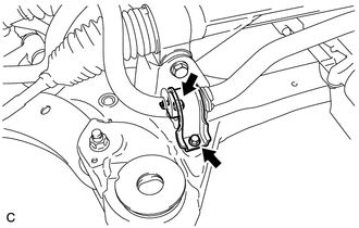
9. SEPARATE FRONT NO. 1 STABILIZER BRACKET LH
|
(a) Remove the 2 bolts and separate the front No. 1 stabilizer bracket LH. |
|
10. SEPARATE FRONT NO. 1 STABILIZER BRACKET RH
HINT:
Perform the same procedure as for the LH side.
11. REMOVE FRONT STABILIZER BAR WITH BRACKET
(a) Remove the front stabilizer bar with bracket from the front frame assembly.
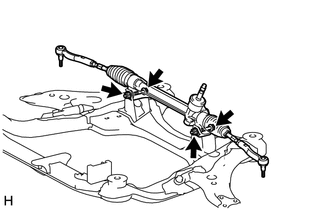
12. REMOVE STEERING LINK ASSEMBLY
|
(a) Remove the 2 bolts, 2 nuts and steering link assembly. NOTICE: Because the nut has its own stopper, do not turn the nut. Loosen the bolt with the nut secured. |
|
13. REMOVE TIE ROD ASSEMBLY LH
|
(a) Put matchmarks on the tie rod assembly LH and steering rack end sub-assembly. Text in Illustration
|
|
.png)
(b) Loosen the lock nut, and remove the tie rod assembly LH and lock nut.
14. REMOVE TIE ROD ASSEMBLY RH
HINT:
Perform the same procedure as for the LH side.
 Components
COMPONENTS
ILLUSTRATION
ILLUSTRATION
ILLUSTRATION
ILLUSTRATION
...
 Disassembly
DISASSEMBLY
PROCEDURE
1. REMOVE STEERING RACK BOOT CLIP (for LH Side)
(a) Using pliers, remove the steering rack boot clip.
2. REMOVE STEERING RACK BOOT CLIP (for RH Side)
HINT:
Perform the same ...
Other materials about Toyota Venza:
Heated Oxygen Sensor
Components
COMPONENTS
ILLUSTRATION
Removal
REMOVAL
PROCEDURE
1. REMOVE NO. 1 ENGINE UNDER COVER
2. REMOVE NO. 2 ENGINE UNDER COVER
3. REMOVE FRONT EXHAUST PIPE ASSEMBLY
4. REMOVE HEATED OXYGEN SENSOR
(a) Using SST, remove the heat ...
Engine Switch Illumination Circuit
DESCRIPTION
The illuminated entry system controls the engine switch illumination.
WIRING DIAGRAM
PROCEDURE
1.
PERFORM ACTIVE TEST USING TECHSTREAM
(a) Connect the Techstream to the DLC3.
(b) Turn the ignition switch to O ...
On-vehicle Inspection
ON-VEHICLE INSPECTION
PROCEDURE
1. INSPECT CAMSHAFT TIMING OIL CONTROL VALVE ASSEMBLY
(a) Connect the Techstream to the DLC3.
(b) Start the engine and turn the Techstream on.
(c) Inspect the oil control valve (for intake camshaft).
(1) Enter the followin ...

0.1505