Toyota Venza: Removal
REMOVAL
CAUTION / NOTICE / HINT
NOTICE:
Do not remove the oil pump or oil pump relief valve from the timing chain cover sub-assembly.
PROCEDURE
1. INSTALL ENGINE ON ENGINE STAND
(See page .gif) )
)
2. REMOVE IGNITION COIL ASSEMBLY
3. REMOVE CYLINDER HEAD COVER SUB-ASSEMBLY
4. REMOVE CRANKSHAFT POSITION SENSOR
5. REMOVE CRANKSHAFT PULLEY
6. REMOVE ENGINE MOUNTING BRACKET RH
|
(a) Remove the 5 bolts and engine mounting bracket RH. |
|
7. REMOVE V-RIBBED BELT TENSIONER ASSEMBLY
8. REMOVE TIMING CHAIN COVER SUB-ASSEMBLY
|
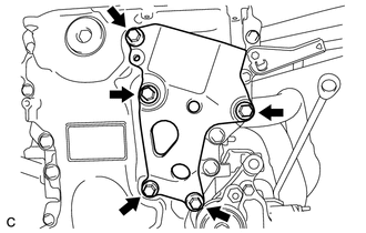
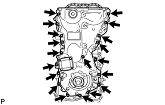
(a) Remove the 17 bolts and 2 nuts. |
|
(b) Remove the timing chain cover sub-assembly by prying between the timing chain cover sub-assembly and cylinder head, camshaft housing, cylinder block and stiffening crankcase with a screwdriver as shown in the illustration.
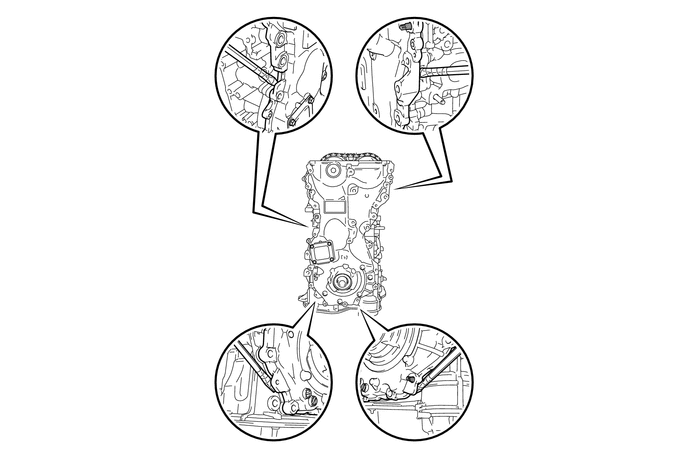
NOTICE:
Be careful not to damage the contact surfaces of the cylinder head, camshaft housing, cylinder block, stiffening crankcase and timing chain cover sub-assembly.
HINT:
Tape the screwdriver tip before use.
|
(c) Remove the 2 oil pump gaskets and oil hole cover gasket from the stiffening crankcase. |
|
.png)
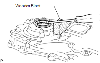
9. REMOVE TIMING CHAIN COVER OIL SEAL
|
(a) Using a screwdriver and wooden block, pry out the timing chain cover oil seal. NOTICE: Do not damage the surface of the timing chain cover oil seal press fit hole. HINT: Tape the screwdriver tip before use. |
|
 Installation
INSTALLATION
PROCEDURE
1. INSTALL TIMING CHAIN COVER SUB-ASSEMBLY
(a) Apply a light coat of engine oil to 2 new oil pump gaskets and new
oil hole cover gasket.
...
 1ar-fe Starting
...
Other materials about Toyota Venza:
Data List / Active Test
DATA LIST / ACTIVE TEST
1. DATA LIST
HINT:
Using the Techstream to read the Data List allows the values or states of switches,
sensors, actuators and other items to be read without removing any parts. This non-intrusive
inspection can be very useful bec ...
Disassembly
DISASSEMBLY
CAUTION / NOTICE / HINT
HINT:
Use an overhaul stand as necessary.
PROCEDURE
1. REMOVE REAR DIFFERENTIAL FILLER PLUG
(a) Remove the rear differential filler plug and gasket.
2. INSPECT ...
Skid Control ECU Malfunction (C1300/62)
DESCRIPTION
The skid control ECU outputs this DTC, if malfunctions are found in the circuit
inside the ECU by self diagnosis.
DTC Code
DTC Detection Condition
Trouble Area
C1300/62
Internal failu ...

0.1281