Toyota Venza: Removal
REMOVAL
PROCEDURE
1. REMOVE FUEL SUCTION TUBE ASSEMBLY WITH PUMP AND GAUGE
(a) Remove the fuel suction tube assembly with pump and gauge (See page
.gif) ).
).
2. REMOVE FUEL SENDER GAUGE
3. REMOVE FUEL FILTER ASSEMBLY
|
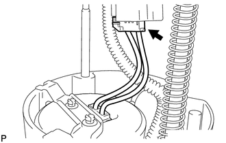
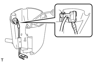
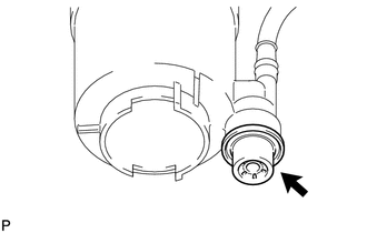
(a) Disconnect the fuel pump connector from the fuel suction plate. NOTICE: Do not damage the wire harness. |
|
|
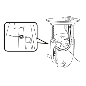
(b) Using needle nose pliers, remove the E-ring. Text in Illustration
NOTICE: Do not disconnect the tube shown in the illustration when disassembling the fuel suction tube assembly with pump and gauge. Doing so will cause reassembly of the fuel suction tube assembly with pump and gauge to be impossible as the tube is welded to the plate. |
|
(c) Separate the fuel suction plate and remove the spring from the sub-tank.
|
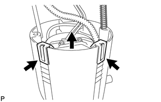
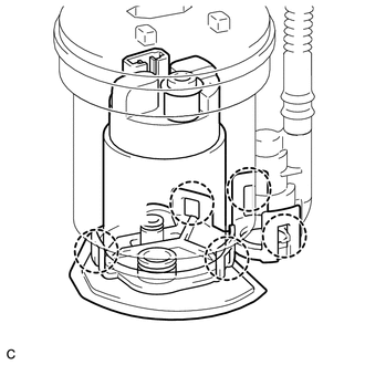
(d) Detach the 2 claws and remove the fuel filter from the sub-tank. |
|
|
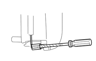
(e) Using a screwdriver with the tip taped, detach the claw of the jet pump nozzle. |
|
|
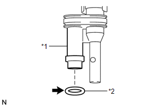
(f) Using a screwdriver with the tip taped, remove the jet pump from the sub-tank. |
|
|
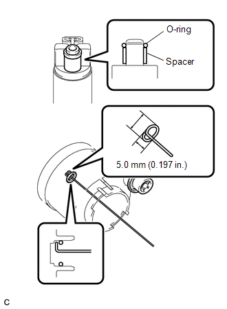
(g) Remove the O-ring from the jet pump. Text in Illustration
|
|
4. REMOVE FUEL PUMP ASSEMBLY WITH FILTER
|
(a) Detach the 5 claws on the filter and remove the fuel pump from the fuel filter. NOTICE:
HINT: If the fuel filter assembly is to be replaced, replace the fuel suction plate sub-assembly. |
|
|
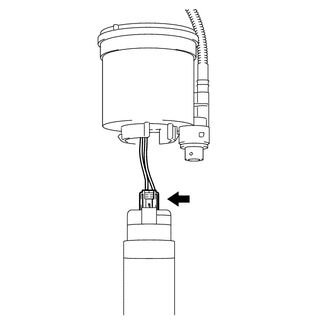
(b) Disconnect the fuel pump connector from the fuel pump and then remove the fuel pump harness. |
|
|
(c) Remove the O-ring and spacer from the fuel pump. NOTICE: Be careful not to damage the sealing surface. HINT: If the O-ring still remains in the fuel filter, remove it using a wire tip (φ1 mm) that is formed as shown in the illustration. |
|
5. REMOVE FUEL PRESSURE REGULATOR ASSEMBLY
|
(a) Remove the fuel pressure regulator from the fuel filter. |
|
(b) Remove the 2 O-rings.
 Components
COMPONENTS
ILLUSTRATION
...
 Installation
INSTALLATION
PROCEDURE
1. INSTALL FUEL PRESSURE REGULATOR ASSEMBLY
(a) Apply a light coat of gasoline to 2 new O-rings, and install them
onto the fuel pressure regulator.
Text in ...
Other materials about Toyota Venza:
Removal
REMOVAL
PROCEDURE
1. REMOVE FRONT DOOR SCUFF PLATE LH
2. REMOVE COWL SIDE TRIM SUB-ASSEMBLY LH
3. REMOVE LOWER NO. 1 INSTRUMENT PANEL FINISH PANEL
4. REMOVE LOWER STEERING COLUMN COVER
(a) Turn the steering wheel assembly to the right ...
Dtc Check / Clear
DTC CHECK / CLEAR
1. CHECK DTC (When Using Techstream)
(a) Check the DTCs.
(1) Connect the Techstream to the DLC3.
(2) Turn the ignition switch to ON.
(3) Turn the Techstream on.
(4) Read the DTCs following the prompts on the Techstream screen. Enter the ...
Head restraints
Head restraints are provided for all seats.
► Front and rear outboard seats
Vertical adjustment 1. Up
Pull the head restraint up.
2. Down
Push the head restraints down while pressing the lock release button.
► Rear center seat (fabric seat) ...

0.1736