Toyota Venza: Installation
INSTALLATION
PROCEDURE
1. INSTALL FUEL PRESSURE REGULATOR ASSEMBLY
|
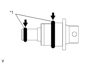
(a) Apply a light coat of gasoline to 2 new O-rings, and install them onto the fuel pressure regulator. Text in Illustration
|
|
|
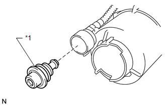
(b) Install the fuel pressure regulator to the fuel filter. Text in Illustration
|
|
2. INSTALL FUEL PUMP ASSEMBLY WITH FILTER
.gif)
3. INSTALL FUEL FILTER ASSEMBLY
4. INSTALL FUEL SENDER GAUGE
5. INSTALL FUEL SUCTION TUBE ASSEMBLY WITH PUMP AND GAUGE
(a) Install the fuel suction tube assembly with pump and gauge (See page
).
 Removal
REMOVAL
PROCEDURE
1. REMOVE FUEL SUCTION TUBE ASSEMBLY WITH PUMP AND GAUGE
(a) Remove the fuel suction tube assembly with pump and gauge (See page
).
2. REMOVE FUEL SENDER GAUGE
3. REMOVE FU ...
 Fuel Pump
...
Other materials about Toyota Venza:
Removal
REMOVAL
PROCEDURE
1. REMOVE FRONT WIPER ARM HEAD CAP
(a) Using a screwdriver, remove the 2 front wiper arm head caps as shown
in the illustration.
Text in Illustration
*1
Protective Tape
...
Replacing a flat tire
Chock the tires.
Slightly loosen the wheel nuts (one turn).
Turn the tire jack portion “A” by hand until the notch of the jack is in contact
with the jack point.
Raise the vehicle until the tire is slightly raised off the ground.
Remove a ...
CD cannot be Ejected
PROCEDURE
1.
CHECK OPERATION
(a) Press the CD eject switch of the navigation receiver assembly for 10 seconds
or more and check that the CD is ejected.
OK:
CD is ejected.
NG
REPLACE NAVIGATION RECEIVER ...

0.1463