Toyota Venza: Disassembly
DISASSEMBLY
PROCEDURE
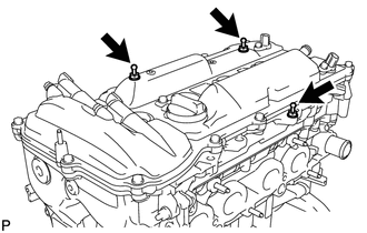
1. REMOVE ENGINE COVER JOINT
|
(a) Remove the 3 joints. |
|
2. REMOVE SPARK PLUG
.gif)
3. REMOVE CAMSHAFT TIMING OIL CONTROL VALVE ASSEMBLY (for Intake Side)
4. REMOVE CAMSHAFT TIMING OIL CONTROL VALVE ASSEMBLY (for Exhaust Side)
5. REMOVE CAMSHAFT POSITION SENSOR (for Intake Side)
6. REMOVE CAMSHAFT POSITION SENSOR (for Exhaust Side)
7. REMOVE OIL FILLER CAP SUB-ASSEMBLY
(a) Remove the oil filler cap from the cylinder head.
(b) Remove the gasket from the oil filler cap.
8. REMOVE CRANKSHAFT POSITION SENSOR
9. REMOVE VENTILATION VALVE SUB-ASSEMBLY
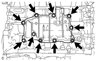
10. REMOVE VENTILATION CASE SUB-ASSEMBLY
|
(a) Remove the 8 bolts and 2 nuts. |
|
|
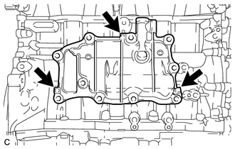
(b) Remove the ventilation case by prying between the ventilation case and cylinder block with a screwdriver. HINT: Tape the screwdriver tip before use. NOTICE: Be careful not to damage the contact surfaces of the cylinder block and ventilation case. |
|
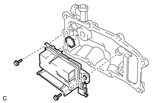
11. REMOVE SEPARATOR CASE
|
(a) Remove the 2 bolts, separator case and gasket. |
|
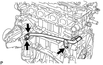
12. REMOVE NO. 1 WATER BY-PASS PIPE
|
(a) Remove the bolt, 2 nuts, water by-pass pipe and gasket. |
|
13. REMOVE WATER INLET
14. REMOVE THERMOSTAT
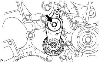
15. REMOVE V-RIBBED BELT TENSIONER ASSEMBLY
|
(a) Remove the bolt and V-ribbed belt tensioner. |
|
16. REMOVE WATER PUMP ASSEMBLY
17. REMOVE OIL COOLER ASSEMBLY (w/ Oil Cooler)
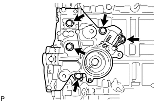
18. REMOVE INLET WATER HOUSING
|
(a) Remove the 4 bolts, nut, inlet water housing and gasket. |
|
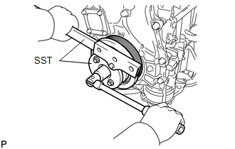
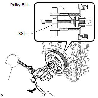
19. REMOVE CRANKSHAFT PULLEY
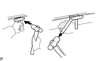
|
(a) Using SST, hold the crankshaft pulley and loosen the pulley bolt. Further loosen the bolt until 2 or 3 threads are screwed into the crankshaft. SST: 09213-54015 SST: 09330-00021 HINT: Part number of installation bolt for SST (crankshaft pulley holding tool): 91551-80650 (quantity: 2) |
|
|
(b) Using SST and the pulley bolt, remove the crankshaft pulley. SST: 09950-50013 09951-05010 09952-05010 09953-05020 09954-05011 HINT: Apply a lubricant to the threads and end of SST. |
|
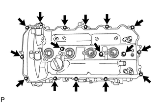
20. REMOVE CYLINDER HEAD COVER SUB-ASSEMBLY
|
(a) Remove the 16 bolts, 3 seal washers, cylinder head cover and gasket. |
|
|
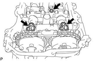
(b) Remove the 3 gaskets from the camshaft bearing caps. |
|
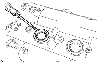
21. REMOVE SPARK PLUG TUBE GASKET
|
(a) Using a screwdriver, pry out the 4 plug tube gaskets. NOTICE: Be careful not to damage the cylinder head cover. HINT: Tape the screwdriver tip before use. |
|
22. REMOVE ENGINE MOUNTING BRACKET RH
23. REMOVE TIMING CHAIN COVER SUB-ASSEMBLY
24. REMOVE TIMING CHAIN COVER TIGHT PLUG
|
(a) Using a 14 mm hexagon wrench, remove the plug and gasket. |
|
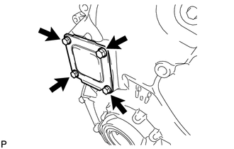
25. REMOVE TIMING CHAIN COVER PLATE
|
(a) Remove the 4 bolts, timing chain cover plate and gasket. |
|
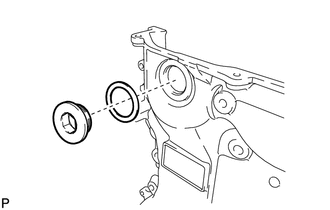
26. REMOVE TIMING CHAIN COVER OIL SEAL
27. SET NO. 1 CYLINDER TO TDC/COMPRESSION
28. REMOVE TIMING CHAIN GUIDE
29. REMOVE NO. 1 CHAIN TENSIONER ASSEMBLY
30. REMOVE CHAIN TENSIONER SLIPPER
31. REMOVE CHAIN SUB-ASSEMBLY
(a) Remove the chain sub-assembly.
32. REMOVE NO. 1 CHAIN VIBRATION DAMPER
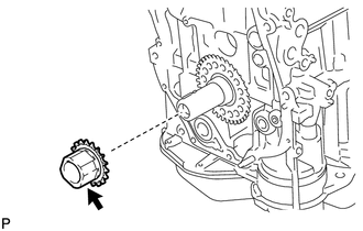
33. REMOVE CRANKSHAFT TIMING SPROCKET
|
(a) Remove the crankshaft timing sprocket from the crankshaft. |
|
34. REMOVE CAMSHAFT TIMING GEAR ASSEMBLY
35. REMOVE CAMSHAFT TIMING EXHAUST GEAR ASSEMBLY
36. REMOVE CAMSHAFT HOUSING SUB-ASSEMBLY
37. REMOVE CAMSHAFT BEARING CAP
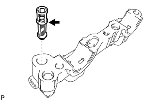
38. REMOVE OIL CONTROL VALVE FILTER
|
(a) Remove the oil control valve filter from the No. 1 camshaft bearing cap. |
|
39. REMOVE CAMSHAFT
40. REMOVE NO. 1 CAMSHAFT BEARING
|
(a) Remove the No. 1 camshaft bearing. |
|
41. REMOVE NO. 2 CAMSHAFT BEARING
|
(a) Remove the No. 2 camshaft bearing. |
|
42. REMOVE CAMSHAFT HOUSING STUD BOLT
NOTICE:
If a stud bolt is deformed or its threads are damaged, replace it.
43. REMOVE CAMSHAFT BEARING CAP SETTING RING PIN
NOTICE:
It is not necessary to remove the ring pin unless it is being replaced.
44. REMOVE CAMSHAFT HOUSING STRAIGHT PIN
NOTICE:
It is not necessary to remove the straight pin unless it is being replaced.
45. REMOVE NO. 1 VALVE ROCKER ARM SUB-ASSEMBLY
46. REMOVE VALVE LASH ADJUSTER ASSEMBLY
47. REMOVE VALVE STEM CAP
48. REMOVE CYLINDER HEAD SUB-ASSEMBLY
49. REMOVE CYLINDER HEAD GASKET
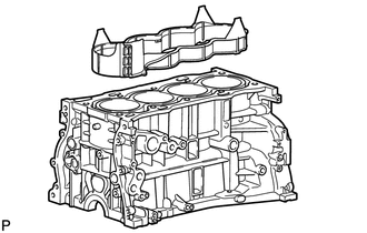
50. REMOVE CYLINDER BLOCK WATER JACKET SPACER
|
(a) Remove the cylinder block water jacket spacer from the cylinder block. NOTICE: Be sure to remove the water jacket spacer. If it is not removed, it may fall and become damaged when the cylinder block is inverted. |
|
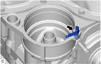
51. REMOVE OIL FILTER CAP ASSEMBLY
52. REMOVE OIL FILTER BRACKET CLIP
|
(a) Remove the oil filter bracket clip from the stiffening crankcase assembly. |
|
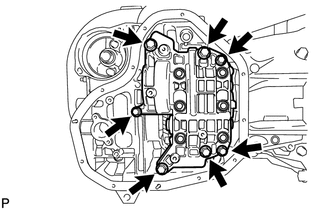
53. REMOVE OIL PAN SUB-ASSEMBLY
|
(a) Remove the 11 bolts and 2 nuts. |
|
|
(b) Insert the blade of an oil pan seal cutter between the oil pan and stiffening crankcase, cut off the applied sealer and remove the oil pan. NOTICE:
|
|
54. REMOVE OIL STRAINER SUB-ASSEMBLY
|
(a) Remove the 3 bolts, oil strainer and gasket. |
|
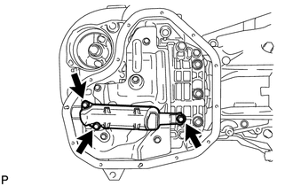
55. REMOVE NO. 1 OIL PAN BAFFLE PLATE
|
(a) Remove the 5 bolts and oil pan baffle plate. |
|
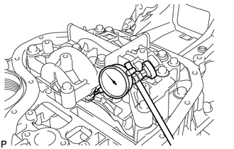
56. INSPECT CRANKSHAFT BACKLASH
|
(a) Using a dial indicator, measure the backlash of the crankshaft and balance shaft as shown in the illustration. Standard backlash: 0.05 to 0.20 mm (0.00197 to 0.00787 in.) Maximum backlash: 0.20 mm (0.00787 in.) If the backlash is more than the maximum, replace the engine balancer assembly. |
|
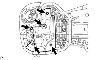
57. REMOVE ENGINE BALANCER ASSEMBLY
|
(a) Remove the 7 bolts and engine balancer. NOTICE: Do not disassemble the engine balancer. |
|
58. INSPECT BALANCE SHAFT THRUST CLEARANCE
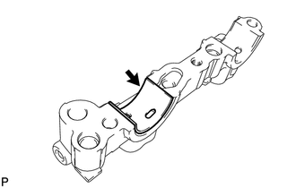
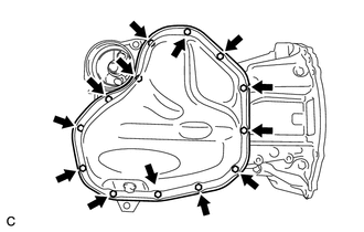
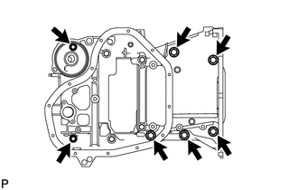
59. REMOVE STIFFENING CRANKCASE ASSEMBLY
|
(a) Remove the 7 bolts. |
|
|
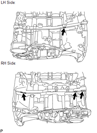
(b) Using a screwdriver, remove the stiffening crankcase by prying between the stiffening crankcase and cylinder block at the places shown in the illustration. HINT: Tape the screwdriver tip before use. NOTICE: Be careful not to damage the contact surfaces of the cylinder block and stiffening crankcase. |
|
60. REMOVE STIFFENING CRANKCASE STUD BOLT
NOTICE:
If a stud bolt is deformed or its threads are damaged, replace it.
61. REMOVE STIFFENING CRANKCASE RING PIN
NOTICE:
It is not necessary to remove the ring pin unless it is being replaced.
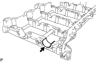
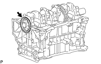
62. REMOVE REAR ENGINE OIL SEAL
|
(a) Remove the rear engine oil seal from the cylinder block. |
|
 Removal
REMOVAL
PROCEDURE
1. REMOVE ENGINE OIL LEVEL DIPSTICK GUIDE
(a) Remove the engine oil level dipstick.
(b) Remove the bolt and engine oil l ...
 Inspection
INSPECTION
PROCEDURE
1. INSPECT NO. 1 VALVE ROCKER ARM SUB-ASSEMBLY
(a) Turn the roller by hand to check that it turns smoothly.
If the roller does not turn smoothly, replace the No. ...
Other materials about Toyota Venza:
Touch Panel Switch does not Function
PROCEDURE
1.
CHECK MULTI-DISPLAY
(a) Check if there is any foreign matter caught between the display and exterior
frame of the multi-display.
OK:
No foreign matter is caught between the display and exterior frame of the m ...
Open or Short Circuit in ABS Solenoid Relay Circuit (C0278/11)
DESCRIPTION
The ABS solenoid relay supplies power to the ABS solenoid and TRAC solenoid.
The solenoid relay is turned on 1.5 seconds after the ignition switch is turned
to ON, and is turned off if an open or short in the solenoid is detected by self
diag ...
Installation
INSTALLATION
PROCEDURE
1. INSTALL AIR CONDITIONING UNIT ASSEMBLY
(a) Install the air conditioning unit assembly with the 3 nuts.
Torque:
9.8 N·m {100 kgf·cm, 87 in·lbf}
NOTICE:
Tighten the nuts in the order shown in the illustration to install the ...

0.1537