Toyota Venza: Remote Up / Down Function does not Operate
DESCRIPTION
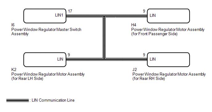
When the ignition switch is ON, the power window regulator master switch assembly sends remote up/down signals to each power window regulator motor assembly via the LIN communication line.
WIRING DIAGRAM
CAUTION / NOTICE / HINT
NOTICE:
The power window control system uses a multiplex communication system (LIN communication
system). Inspect the communication function by following How to Proceed with Troubleshooting
(See page .gif) ). Troubleshoot the power window control
). Troubleshoot the power window control
system after confirming that the communication system is functioning properly.
PROCEDURE
|
1. |
READ VALUE USING TECHSTREAM (Main Body) |
(a) Connect the Techstream to the DLC3.
(b) Turn the ignition switch to ON.
(c) Turn the Techstream on.
(d) Enter the following menus: Body Electrical / Main Body / Data List.
(e) Read the Data List according to the display on the Techstream.
Main Body (Main Body ECU (Driver Side Junction Block Assembly))|
Tester Display |
Measurement Item/Range |
Normal Condition |
Diagnostic Note |
|---|---|---|---|
|
Communication P-Door Motor |
Connection status between power window regulator motor (for front passenger side) and main body ECU (driver side junction block assembly) / OK or STOP |
OK: Normal communication STOP: Communication stopped |
- |
|
Communication RL-Door Motor |
Connection status between power window regulator motor (for rear LH) and main body ECU (driver side junction block assembly) / OK or STOP |
OK: Normal communication STOP: Communication stopped |
- |
|
Communication RR-Door Motor |
Connection status between power window regulator motor (for rear RH) and main body ECU (driver side junction block assembly) / OK or STOP |
OK: Normal communication STOP: Communication stopped |
- |
|
Communication Master SW |
Connection status between power window master switch and main body ECU (driver side junction block assembly) / OK or STOP |
OK: Normal communication STOP: Communication stopped |
- |
OK:
On the Techstream screen, OK is displayed.
| NG | .gif) |
GO TO LIN COMMUNICATION SYSTEM (Proceed to How to Proceed with Troubleshooting) |
|
.gif)
|
2. |
READ VALUE USING TECHSTREAM (Master Switch) |
(a) Enter the following menus: Body Electrical / Master Switch / Data List.
(b) Read the Data List according to the display on the Techstream.
Master Switch (Power Window Regulator Master Switch Assembly)|
Tester Display |
Measurement Item/Range |
Normal Condition |
Diagnostic Note |
|---|---|---|---|
|
P Door P/W Auto SW |
Front passenger side power window auto up/down switch signal / ON or OFF |
ON: Front passenger door power window auto switch operated OFF: Front passenger door power window auto switch not operated |
- |
|
RL Door P/W Auto SW |
Rear LH side power window auto up/down switch signal / ON or OFF |
ON: Rear LH power window auto switch operated OFF: Rear LH power window auto switch not operated |
- |
|
RR Door P/W Auto SW |
Rear RH side power window auto up/down switch signal / ON or OFF |
ON: Rear RH power window auto switch operated OFF: Rear RH power window auto switch not operated |
- |
|
P Door P/W Up SW |
Front passenger side power window manual up switch signal / ON or OFF |
ON: Front passenger door power window manual up switch operated OFF: Front passenger door power window manual up switch not operated |
- |
|
RL Door P/W Up Switch |
Rear LH side power window manual up switch signal / ON or OFF |
ON: Rear LH power window manual up switch operated OFF: Rear LH power window manual up switch not operated |
- |
|
RR Door P/W Up Switch |
Rear RH side power window manual up switch signal / ON or OFF |
ON: Rear RH power window manual up switch operated OFF: Rear RH power window manual up switch not operated |
- |
|
P Door P/W Down SW |
Front passenger side power window manual down switch signal / ON or OFF |
ON: Front passenger door power window manual down switch operated OFF: Front passenger door power window manual down switch not operated |
- |
|
RL Door P/W Down SW |
Rear LH side power window manual down switch signal / ON or OFF |
ON: Rear LH power window manual down switch operated OFF: Rear LH power window manual down switch not operated |
- |
|
RR Door P/W Down SW |
Rear RH side power window manual down switch signal / ON or OFF |
ON: Rear RH power window manual down switch operated OFF: Rear RH power window manual down switch not operated |
- |
|
Window Lock Switch Status |
Window lock switch signal / ON or OFF |
ON: Window lock switch LOCK position OFF: Window lock switch UNLOCK position |
- |
OK:
On the Techstream screen, ON or OFF is displayed accordingly.
|
Result |
Proceed to |
|---|---|
|
NG |
A |
|
OK (Front passenger side power window remote up/down function does not operate) |
B |
|
OK (Rear LH side power window remote up/down function does not operate) |
C |
|
OK (Rear RH side power window remote up/down function does not operate) |
D |
| A | |
REPLACE POWER WINDOW REGULATOR MASTER SWITCH ASSEMBLY |
| B | |
REPLACE POWER WINDOW REGULATOR MOTOR ASSEMBLY (for Front Passenger Side) |
| C | |
REPLACE POWER WINDOW REGULATOR MOTOR ASSEMBLY (for Rear LH Side) |
| D | |
REPLACE POWER WINDOW REGULATOR MOTOR ASSEMBLY (for Rear RH Side) |
 Glass Position Initialization Incomplete (B2313)
DESCRIPTION
The power window regulator motor assembly is operated by the power window regulator
master switch assembly or power window regulator switch assembly. The power window
regulator motor ...
 Driver Side Power Window does not Operate with Power Window Master Switch
DESCRIPTION
When the engine is running or the ignition switch is ON, the power window regulator
motor assembly (for driver side) is operated by the power window regulator master
switch assembly. ...
Other materials about Toyota Venza:
Disposal
DISPOSAL
CAUTION / NOTICE / HINT
CAUTION:
Before performing pre-disposal deployment of any SRS part, review and closely
follow all applicable environmental and hazardous material regulations. Pre-disposal
deployment may be considered hazardous material ...
Clearance Sonar Main Switch
Components
COMPONENTS
ILLUSTRATION
Removal
REMOVAL
PROCEDURE
1. REMOVE FRONT DOOR SCUFF PLATE LH
2. REMOVE COWL SIDE TRIM SUB-ASSEMBLY LH
3. REMOVE LOWER NO. 1 INSTRUMENT PANEL FINISH PANEL
4. REMOVE CLEARANCE SONAR MAIN SWITCH
...
Engine Oil Cooler
Components
COMPONENTS
ILLUSTRATION
Removal
REMOVAL
PROCEDURE
1. REMOVE EXHAUST MANIFOLD ASSEMBLY
HINT:
See page
2. DRAIN ENGINE OIL
3. DRAIN ENGINE COOLANT
4. REMOVE OIL COOLER ASSEMBLY
(a) Remove the nut, union bolt, seal ...

0.1371