Toyota Venza: Relay
On-vehicle Inspection
ON-VEHICLE INSPECTION
PROCEDURE
1. INSPECT HORN RELAY (ENGINE ROOM JUNCTION BLOCK ASSEMBLY)
|
(a) Remove the engine room junction block assembly from the engine room
relay block (See page |
|
.gif) ).
).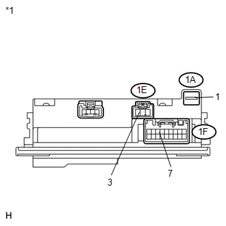
(b) Connect a positive (+) lead from the battery to terminal 1A-1.
(c) Connect a negative (-) lead from the battery to terminal 1F-7.
(d) Measure the voltage according to the value(s) in the table below.
Standard Voltage:
|
Tester Connection |
Condition |
Specified Condition |
|---|---|---|
|
1E-3 - Battery negative |
Always |
11 to 14 V |
|
*1 |
Component without harness connected (Engine Room Junction Block Assembly) |
If the result is not as specified, replace the engine room junction block assembly.
 Horn System
Precaution
PRECAUTION
NOTICE:
When disconnecting the cable from the negative (-) battery terminal, initialize
the following system after the cable is reconnected.
System Name
...
 Lighting (ext)
...
Other materials about Toyota Venza:
Removal
REMOVAL
CAUTION / NOTICE / HINT
HINT:
Use the same procedure for the RH side and LH side.
The procedure listed below is for the LH side.
PROCEDURE
1. PRECAUTION
CAUTION:
Be sure to read Precaution thoroughly before servicing (See page
...
Diagnostic Trouble Code Chart
DIAGNOSTIC TROUBLE CODE CHART
If a trouble code is displayed during the DTC check, check the trouble areas
listed for that code in the table below and proceed to the appropriate page.
Cruise Control System
DTC Code
Detection Item
...
ACIS Control Circuit
DESCRIPTION
This circuit opens and closes the Intake Air Control Valve (IACV) in response
to the engine load in order to increase the intake efficiency (ACIS: Acoustic Control
Induction System).
WIRING DIAGRAM
CAUTION / NOTICE / HINT
NOTICE:
Inspe ...

0.1688