Toyota Venza: Reassembly
REASSEMBLY
PROCEDURE
1. INSTALL TRANSFER DRIVEN PINION REAR BEARING
|
(a) Using SST and a press, press the transfer driven pinion rear bearing (outer race) to the case. SST: 09950-60010 09951-00620 SST: 09950-70010 09951-07150 NOTICE: Keep the transfer case horizontal using wooden blocks, etc. |
|
(b) Apply gear oil to the transfer driven pinion rear bearing (outer race).
2. INSTALL TRANSFER OUTPUT SHAFT WASHER
(a) Install the transfer output shaft washer to the transfer case.
HINT:
Install the same transfer output shaft washer as the one removed.
(b) Apply gear oil to the transfer output shaft washer.
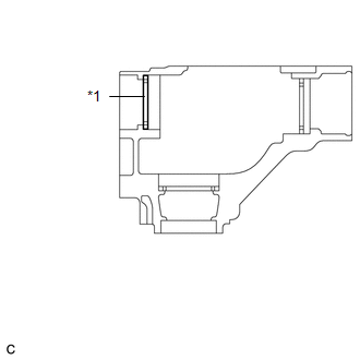
3. INSTALL TRANSFER DRIVEN PINION FRONT BEARING
|
(a) Apply gear oil to the inner surface of the transfer case. |
|
(b) Using SST, install the transfer driven pinion front bearing (outer race) to the transfer case.
SST: 09950-60010
09951-00610
09951-00620
09951-00650
SST: 09950-60020
09951-00680
Text in Illustration|
*1 |
Transfer Driven Pinion Front Bearing (Outer Race) |
|
*a |
Turn |
|
*b |
Hold |
|
(c) Using SST and a press, press the transfer driven pinion front bearing (inner race) into the driven pinion. SST: 09506-30012 |
|
4. INSTALL DRIVEN PINION
|
(a) Install the driven pinion to the transfer case. |
|
|
(b) Install a new transfer pinion bearing spacer and the transfer driven pinion rear bearing (inner race) to the driven pinion. HINT: Install the transfer pinion bearing spacer with the larger inner diameter facing forward as shown in the illustration. |
|
|
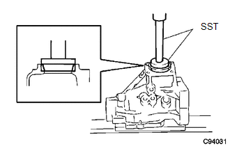
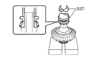
(c) Using SST, install a new gear nut. SST: 09326-20011 SST: 09556-16030 Torque: Specified tightening torque : 270-420 N·m {2753-4283 kgf·cm, 199-310 ft·lbf} Text in Illustration
NOTICE: Do not stake the gear nut until the final preload, tooth contact and backlash adjustments are completed. HINT:
|
|
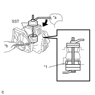
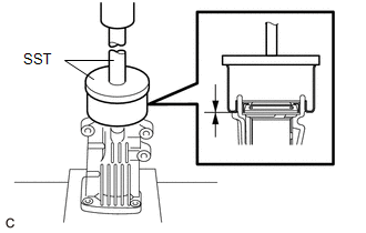
5. ADJUST DRIVEN PINION PRELOAD
|
(a) Using SST and a torque wrench, measure the driven pinion preload. SST: 09326-20011 Text in Illustration
Specified Preload (at Starting):
NOTICE:
HINT:
|
|
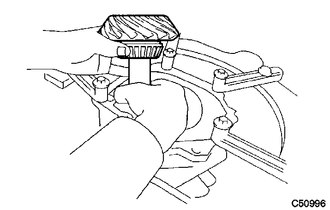
6. INSTALL RING GEAR
(a) Clean the contact surfaces of the ring gear and transfer ring gear mounting case.
|
(b) Heat the ring gear in boiling water. Text in Illustration
|
|
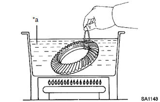
(c) Carefully remove the ring gear from the boiling water.
(d) Secure the transfer ring gear mounting case in a vise using aluminum plates.
NOTICE:
Be careful not to damage the transfer ring gear mounting case in the vise.
|
(e) After the moisture on the ring gear has completely evaporated, quickly align the matchmarks and set the ring gear to the transfer ring gear mounting case. Text in Illustration
|
|
.png)
(f) Apply adhesive to the 12 new bolts.
Adhesive:
Toyota Genuine Adhesive 1324, Three Bond 1324 or equivalent
(g) Install the 12 bolts.
Torque:
99 N·m {1005 kgf·cm, 73 ft·lbf}
NOTICE:
- Tighten the bolts evenly in a diagonal pattern using several steps.
- Tighten the bolts after the ring gear has cooled down sufficiently.
- In order to ensure proper sealing of the bolts, apply adhesive to the bolts and install them within 10 minutes of adhesive application.
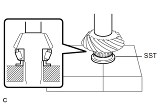
7. INSTALL RING GEAR MOUNTING CASE BEARING
|
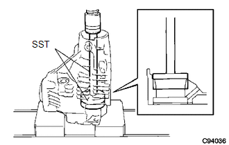
(a) Using SST and a press, press the ring gear mounting case bearing (inner race) to the transfer ring gear mounting case. SST: 09387-00010 SST: 09950-70010 09951-07100 |
|
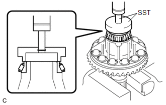
(b) Install the ring gear mounting case bearing (outer race) to the transfer ring gear mounting case.
(c) Apply gear oil to the ring gear mounting case bearing.
|
(d) Using SST and a press, press the ring gear mounting case bearing (inner race) to the transfer ring gear mounting case. SST: 09223-00010 SST: 09726-40010 |
|
(e) Install the ring gear mounting case plate washer to the case.
HINT:
If replacing the case plate washer, use one with the same thickness as the one removed.
|
(f) Using SST and a press, press the ring gear mounting case bearing (outer race) into the transfer case. SST: 09950-60010 09951-00680 SST: 09950-70010 09951-07200 |
|
(g) Apply gear oil to the ring gear mounting case bearing.
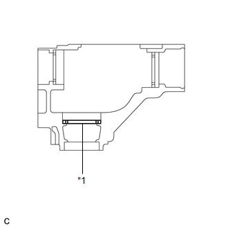
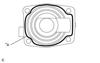
8. INSTALL TRANSFER RING GEAR MOUNTING CASE
|
(a) Apply gear oil to the transfer ring gear mounting case. |
|
.png)
(b) Install the transfer ring gear mounting case to the transfer case.
9. INSTALL NO. 1 TRANSFER OUTPUT SHAFT SPACER
|
(a) Align the cutout on the No. 1 transfer output shaft spacer with the transfer case hole to install it as shown in the illustration. Text in Illustration
|
|
10. INSTALL NO. 2 TRANSFER RING GEAR MOUNTING CASE WASHER
|
(a) Using a brass bar and a hammer, install the No. 2 transfer ring gear mounting case washer. HINT: Use a No. 2 transfer ring gear mounting case washer with the same thickness as the one removed. |
|
11. INSTALL BEARING CAP
|
(a) Install the bearing cap with the 2 bolts. Torque: 63 N·m {644 kgf·cm, 47 ft·lbf} |
|
.png)
12. INSPECT RING GEAR BACKLASH
|
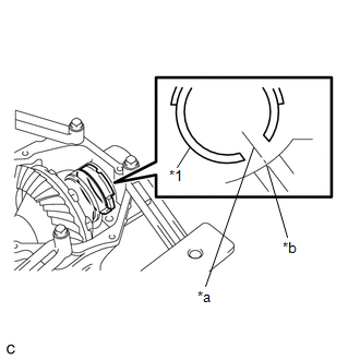
(a) Set a dial indicator perpendicular to a ring gear tooth tip. Secure the driven pinion in place and move the ring gear back and forth to measure the backlash. Backlash: 0.14 to 0.25 mm (0.00551 to 0.00984 in.) NOTICE: Check at least 3 positions on the circumference of the ring gear. |
|
.png)
|
(b) If the backlash is outside the specified range, select a ring gear mounting case washer from the table and install it to meet the specified range. Text in Illustration
|
|
13. INSPECT TOOTH CONTACT BETWEEN RING GEAR AND DRIVEN PINION
|
(a) Coat 3 or 4 teeth at 4 different positions on the ring gear with Prussian blue. |
|
.png)
(b) Rotate the ring gear 10 times or more.
(c) Rotate the ring gear to inspect the tooth contact pattern.
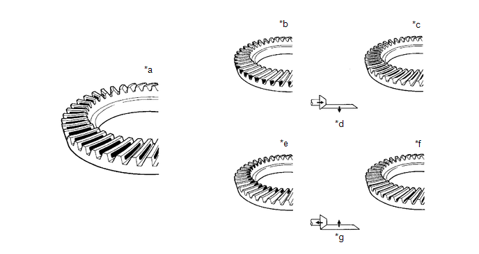 Text in Illustration
|
*a |
Proper Contact |
*b |
Heel Contact |
|
*c |
Face Contact |
*d |
Select a washer that will bring the driven pinion closer to the ring gear |
|
*e |
Toe Contact |
*f |
Flank Contact |
|
*g |
Select a washer that will shift the driven pinion away from the ring gear |
- |
- |
|
(d) If the tooth contact pattern is not correct, select a new transfer output shaft washer that is thicker or thinner as necessary and recheck. Text in Illustration
NOTICE: When the washer thickness is changed, readjust the backlash (See page
|
|
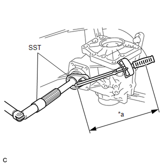
14. INSPECT AND ADJUST TOTAL PRELOAD
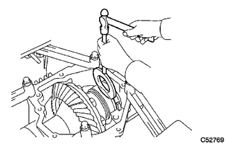
(a) Using SST and a torque wrench, measure the total preload.
SST: 09326-20011
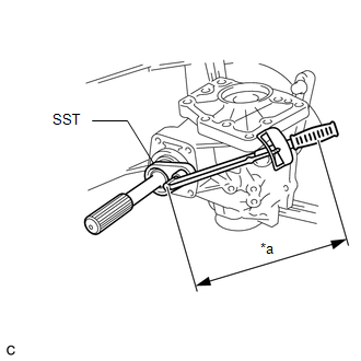 Text in Illustration
|
*a |
Torque Wrench Fulcrum Length |
Specified Total Preload (at Starting):
|
Item |
Preload |
|---|---|
|
New bearing |
0.48 to 0.70 N*m (5 to 7 kgf*cm, 5 to 6 in.*lbf) + Driven pinion preload |
|
Reused bearing |
0.35 to 0.53 N*m (4 to 5 kgf*cm, 4 to 4.6 in.*lbf) + Driven pinion preload |
NOTICE:
Turn the driven pinion counterclockwise and clockwise several times.
HINT:
- Calculate the torque wrench reading when changing the fulcrum length
of the torque wrench (See page
.gif) ).
).
- When using SST (fulcrum length of 50 mm (1.97 in.)) + torque wrench
(fulcrum length of 130 mm (5.12 ft.)):
Total Preload (at Starting):
Item
Preload
New bearing
0.35 to 0.50 N*m (4 to 5 kgf*cm, 4 to 4.4 in.*lbf) + Driven pinion preload
Reused bearing
0.25 to 0.38 N*m (3 to 3.8 kgf*cm, 3 to 3.3 in.*lbf) + Driven pinion preload
If the preload is outside the specified range, replace the No. 2 transfer ring gear mounting case washer with one that is thicker or thinner as necessary and recheck.
.png) Text in Illustration
Text in Illustration
|
*1 |
No. 2 Transfer Ring Gear Mounting Case Washer |
|
Mark |
Thickness (mm (in.)) |
Mark |
Thickness (mm (in.)) |
|---|---|---|---|
|
G7 |
2.47 (0.0972) |
M7 |
3.47 (0.1366) |
|
G8 |
2.49 (0.0980) |
M8 |
3.49 (0.1374) |
|
G9 |
2.51 (0.0988) |
M9 |
3.51 (0.1382) |
|
H0 |
2.53 (0.0996) |
N0 |
3.53 (0.1390) |
|
H1 |
2.55 (0.1004) |
N1 |
3.55 (0.1398) |
|
H2 |
2.57 (0.1012) |
N2 |
3.57 (0.1406) |
|
H3 |
2.59 (0.1020) |
N3 |
3.59 (0.1413) |
|
H4 |
2.61 (0.1028) |
N4 |
3.61 (0.1421) |
|
H5 |
2.63 (0.1035) |
N5 |
3.63 (0.1429) |
|
H6 |
2.65 (0.1043) |
N6 |
3.65 (0.1437) |
|
H7 |
2.67 (0.1051) |
N7 |
3.67 (0.1445) |
|
H8 |
2.69 (0.1059) |
N8 |
3.69 (0.1453) |
|
H9 |
2.71 (0.1067) |
N9 |
3.71 (0.1461) |
|
J0 |
2.73 (0.1075) |
P0 |
3.73 (0.1469) |
|
J1 |
2.75 (0.1083) |
P1 |
3.75 (0.1476) |
|
J2 |
2.77 (0.1091) |
P2 |
3.77 (0.1484) |
|
J3 |
2.79 (0.1098) |
P3 |
3.79 (0.1492) |
|
J4 |
2.81 (0.1106) |
P4 |
3.81 (0.1500) |
|
J5 |
2.83 (0.1114) |
P5 |
3.83 (0.1508) |
|
J6 |
2.85 (0.1122) |
P6 |
3.85 (0.1516) |
|
J7 |
2.87 (0.1130) |
P7 |
3.87 (0.1524) |
|
J8 |
2.89 (0.1138) |
P8 |
3.89 (0.1531) |
|
J9 |
2.91 (0.1146) |
P9 |
3.91 (0.1539) |
|
K0 |
2.93 (0.1154) |
Q0 |
3.93 (0.1547) |
|
K1 |
2.95 (0.1161) |
Q1 |
3.95 (0.1555) |
|
K2 |
2.97 (0.1169) |
Q2 |
3.97 (0.1563) |
|
K3 |
2.99 (0.1177) |
Q3 |
3.99 (0.1571) |
|
K4 |
3.01 (0.1185) |
Q4 |
4.01 (0.1579) |
|
K5 |
3.03 (0.1193) |
Q5 |
4.03 (0.1587) |
|
K6 |
3.05 (0.1201) |
Q6 |
4.05 (0.1594) |
|
K7 |
3.07 (0.1209) |
Q7 |
4.07 (0.1602) |
|
K8 |
3.09 (0.1217) |
Q8 |
4.09 (0.1610) |
|
K9 |
3.11 (0.1224) |
Q9 |
4.11 (0.1618) |
|
L0 |
3.13 (0.1232) |
R0 |
4.13 (0.1626) |
|
L1 |
3.15 (0.1240) |
R1 |
4.15 (0.1634) |
|
L2 |
3.17 (0.1248) |
R2 |
4.17 (0.1642) |
|
L3 |
3.19 (0.1256) |
R3 |
4.19 (0.1650) |
|
L4 |
3.21 (0.1264) |
R4 |
4.21 (0.1657) |
|
L5 |
3.23 (0.1272) |
R5 |
4.23 (0.1665) |
|
L6 |
3.25 (0.1280) |
R6 |
4.25 (0.1673) |
|
L7 |
3.27 (0.1287) |
R7 |
4.27 (0.1681) |
|
L8 |
3.29 (0.1295) |
R8 |
4.29 (0.1689) |
|
L9 |
3.31 (0.1303) |
R9 |
4.31 (0.1697) |
|
M0 |
3.33 (0.1311) |
S0 |
4.33 (0.1705) |
|
M1 |
3.35 (0.1319) |
S1 |
4.35 (0.1713) |
|
M2 |
3.37 (0.1327) |
S2 |
4.37 (0.1720) |
|
M3 |
3.39 (0.1335) |
S3 |
4.39 (0.1728) |
|
M4 |
3.41 (0.1343) |
S4 |
4.41 (0.1736) |
|
M5 |
3.43 (0.1350) |
S5 |
4.43 (0.1744) |
|
M6 |
3.45 (0.1358) |
S6 |
4.45 (0.1752) |
|
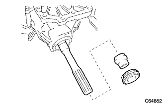
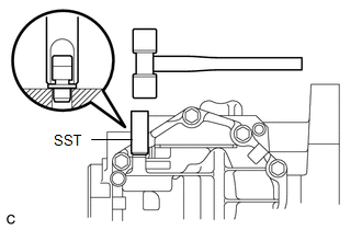
(b) Using a chisel and a hammer, stake the gear nut. |
|
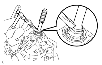
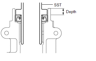
15. INSTALL TRANSFER CASE FRONT OIL SEAL (for RH Side)
|
(a) Using SST and a hammer, drive a new transfer case front oil seal into the case until it reaches the position shown in the illustration. SST: 09950-60010 09951-00350 09951-00580 09952-06010 SST: 09950-70010 09951-07150 Drive in depth: 33.5 to 34.5 mm (1.319 to 1.358 in.) NOTICE: Make sure that the transfer case front oil seal is not tilted. |
|
(b) Apply a small amount of MP grease to the lip of the transfer case front oil seal.
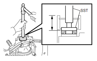
16. INSTALL TRANSFER CASE FRONT OIL SEAL
|
(a) Using SST and a hammer, drive a new transfer case front oil seal into the transfer case until it reaches the position in the illustration. SST: 09608-10010 SST: 09950-70010 09951-07150 Drive in depth: 9.5 to 10.5 mm (0.374 to 0.413 in.) |
|
(b) Apply a small amount of MP grease to the lip of the transfer case front oil seal.
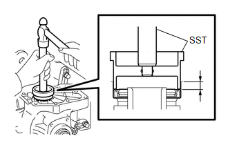
17. INSTALL TRANSFER CASE REAR OIL SEAL
|
(a) Using SST and a hammer, drive a new transfer case rear oil seal into the extension housing until it reaches the position shown in the illustration. SST: 09325-20010 Drive in depth: 9.8 to 10.6 mm (0.386 to 0.417 in.) |
|
(b) Apply a small amount of MP grease to the lip of the transfer case rear oil seal.
18. INSTALL TRANSFER EXTENSION HOUSING DUST DEFLECTOR
|
(a) Using SST and a press, press in a new transfer extension housing dust deflector until it contacts the installation surface as shown in the illustration. SST: 09950-60020 09951-01030 SST: 09950-70010 09951-07150 |
|
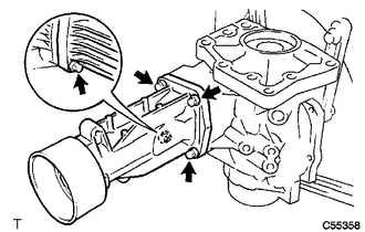
19. INSTALL TRANSFER EXTENSION HOUSING SUB-ASSEMBLY
|
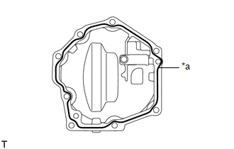
(a) Remove any FIPG material and be careful not to drop oil on the contact surfaces of the transfer extension housing sub-assembly and the transfer case. Text in Illustration
|
|
(b) Degrease the surfaces with a non-residue solvent.
(c) Apply FIPG to the transfer extension housing sub-assembly.
FIPG:
Toyota Genuine Seal Packing 1281, Three Bond 1281 or equivalent
|
(d) Install the transfer extension housing sub-assembly with the 4 bolts to the transfer case. Torque: 26 N·m {260 kgf·cm, 19 ft·lbf} NOTICE: Assemble the transfer extension housing sub-assembly within 10 minutes of FIPG application. |
|
20. SEPARATE TRANSFER ASSEMBLY
(a) Remove the transfer assembly from the overhaul attachment.
21. INSTALL TRANSFER CASE STRAIGHT PIN
(a) Using a plastic hammer, drive the 4 transfer case straight pins into the transfer case positions shown in the illustration.
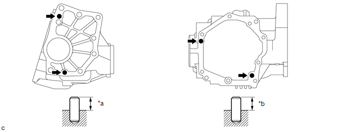 Text in Illustration
|
*a |
10.8 to 11.8 mm (0.425 to 0.465 in.) |
*b |
5.7 to 6.7 mm (0.224 to 0.264 in.) |
22. INSTALL TRANSFER DYNAMIC DAMPER (for 1AR-FE)
|
(a) Install the transfer dynamic damper with the 3 bolts to the transfer extension housing sub-assembly. Torque: 26 N·m {260 kgf·cm, 19 ft·lbf} |
|
.png)
23. INSTALL TRANSFER CASE BREATHER PLUG
|
(a) Using SST and a hammer, tap in a new transfer case breather plug. SST: 09820-00031 |
|
24. INSTALL BREATHER OIL DEFLECTOR
|
(a) Install the breather oil deflector with the bolt. Torque: 6.5 N·m {66 kgf·cm, 58 in·lbf} |
|
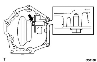
25. INSTALL NO. 1 TRANSFER CASE COVER
|
(a) Remove any FIPG material and be careful not to drop oil on the contact surfaces of the No. 1 transfer case cover and the transfer case. Text in Illustration
|
|
(b) Degrease the surfaces with a non-residue solvent.
(c) Apply FIPG to the No. 1 transfer case cover.
FIPG:
Toyota Genuine Seal Packing 1281, Three Bond 1281 or equivalent
|
(d) Install the No. 1 transfer case cover with the 6 bolts. Torque: 20 N·m {200 kgf·cm, 14 ft·lbf} NOTICE:
|
|
|
(e) Install the No. 1 transfer case cover with 2 new bolts. Torque: 20 N·m {200 kgf·cm, 14 ft·lbf} |
|
26. INSTALL TRANSFER DRAIN PLUG
|
(a) Install a new gasket to the transfer drain plug. |
|
.png)
(b) Install the transfer drain plug to the transfer assembly.
Torque:
49 N·m {500 kgf·cm, 36 ft·lbf}
27. INSTALL NO. 1 TRANSFER CASE PLUG
|
(a) Install a new gasket to the No. 1 transfer case plug. |
|
.png)
(b) Install the No. 1 transfer case plug to the transfer assembly.
Torque:
49 N·m {500 kgf·cm, 36 ft·lbf}
28. INSTALL NO. 2 TRANSFER CASE PLUG
|
(a) Install a new gasket to the No. 2 transfer case plug. |
|
.png)
(b) Install the No. 2 transfer case plug to the transfer assembly.
Torque:
49 N·m {500 kgf·cm, 36 ft·lbf}
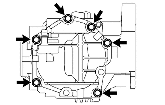
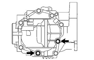
29. INSTALL TRANSFER AND TRANSAXLE SETTING STUD BOLT
(a) Install 4 new transfer and transaxle setting stud bolts to the transfer case positions shown in the illustration.
Torque:
Stud Bolt (A) :
39.2 N·m {400 kgf·cm, 29 ft·lbf}
Stud Bolt (B) :
25 N·m {255 kgf·cm, 18 ft·lbf}
HINT:
Install the shorter end of the stud bolts to the transfer assembly.
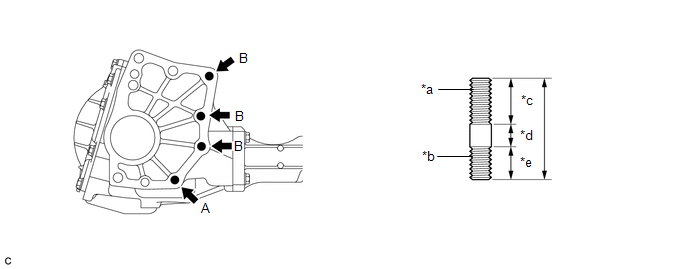 Text in Illustration
|
*a |
Transaxle Side |
*b |
Transfer Side |
|
*c |
30 mm (1.1811 in.) |
*d |
12 mm (0.4724 in.) |
|
*e |
22 mm (0.8661 in.) |
- |
- |
 Inspection
INSPECTION
PROCEDURE
1. INSPECT PRELOAD
(a) Using SST and a torque wrench, measure the preload of the backlash
between the driven pinion and ring gear.
SST: 09326-20011
Preload ...
 Installation
INSTALLATION
PROCEDURE
1. INSTALL TRANSFER ASSEMBLY
(a) Install the transfer assembly to the transaxle assembly with 2 new
bolts and the 6 nuts.
Torque:
69 N·m {700 kgf·cm, ...
Other materials about Toyota Venza:
Removal
REMOVAL
PROCEDURE
1. DISCONNECT CABLE FROM NEGATIVE BATTERY TERMINAL
NOTICE:
When disconnecting the cable, some systems need to be initialized after the cable
is reconnected (See page ).
2. RECOVER REFRIGERANT FROM REFRIGERATION SYSTEM
3. REMOVE CO ...
Receiver Error (C2176/76)
DESCRIPTION
The signals are transmitted to the tire pressure warning antenna and receiver
on the body as radio waves and then sent to the tire pressure warning ECU.
DTC No.
DTC Detection Condition
Trouble Area
...
Diagnosis System
DIAGNOSIS SYSTEM
1. DESCRIPTION
When troubleshooting a vehicle with a diagnosis system, the only difference from
the usual troubleshooting procedure is connecting the Techstream to the vehicle
and reading various data output from the vehicle's skid c ...

0.1601