Toyota Venza: Rear Wiper Rubber
Components
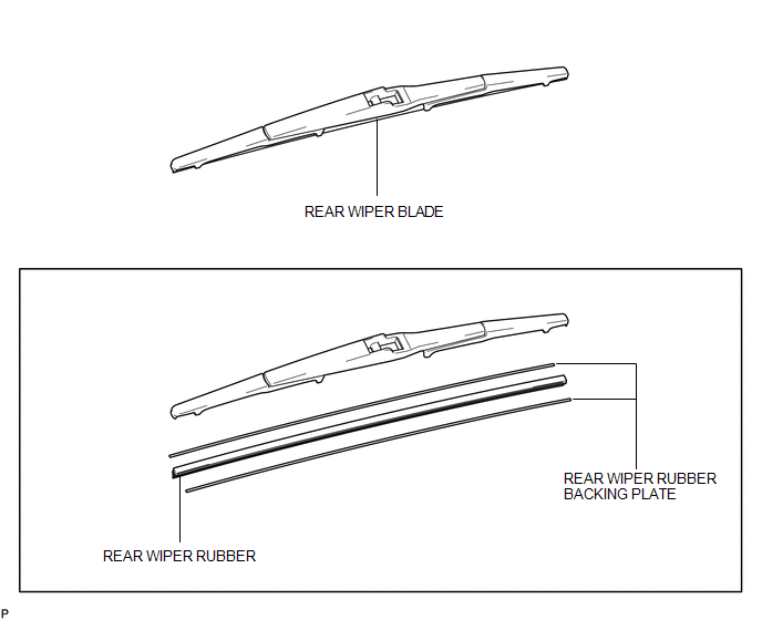
COMPONENTS
ILLUSTRATION
Replacement
REPLACEMENT
PROCEDURE
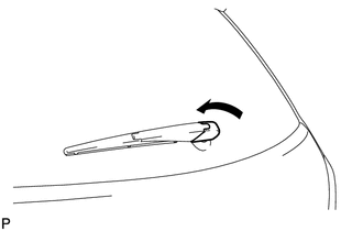
1. REMOVE REAR WIPER BLADE
|
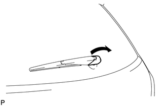
(a) Disconnect the rear wiper arm head cap. |
|
|
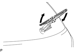
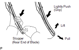
(b) Raise the wiper blade to the position where the claw detaches with a click sound, as shown in the illustration. NOTICE: Be careful not to damage the claw. |
|
|
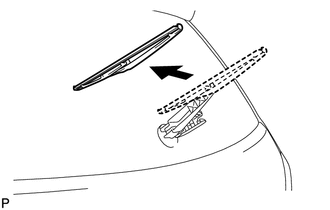
(c) Pull the wiper blade straight toward the left side of the vehicle to remove it from the wiper arm. NOTICE: Do not lower the wiper arm with the wiper blade removed. The arm tip may damage the back door glass surface. |
|
2. REMOVE REAR WIPER RUBBER
|
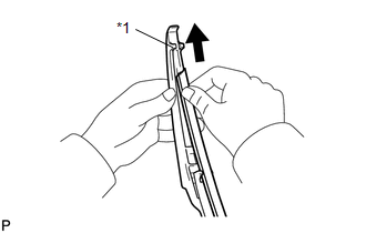
(a) Lift and pull the end of the wiper rubber protrusion from the blade stopper as shown in the illustration. NOTICE: Do not forcibly pull out the wiper rubber. The backing plates will be deformed or the blade claws will be damaged. HINT: Lightly pushing the rubber in the middle will allow it to be removed more easily. |
|
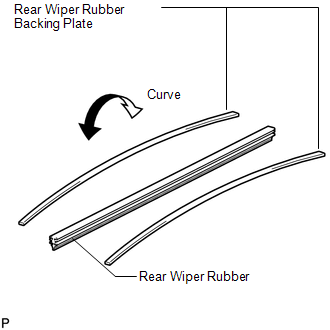
(b) Remove the rear wiper rubber backing plates.
3. INSTALL REAR WIPER RUBBER
|
(a) Install the rear wiper rubber backing plates as shown in the illustration. NOTICE: Install the backing plates facing the correct direction. |
|
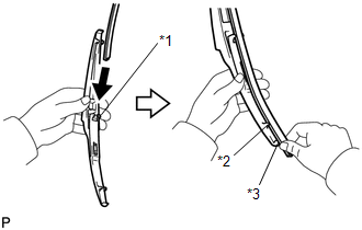
(b) Insert the wiper rubber from the front end of the wiper blade to the rear end through the second claw.
|
(c) After pushing the wiper rubber through the rear end claw, allow it to stick out from the rear end stopper. Text in Illustration
|
|
|
(d) Slide the wiper rubber through the front end claw. Text in Illustration
|
|
4. INSTALL REAR WIPER BLADE
|
(a) Push the wiper blade straight toward the right side of the vehicle to install it to the wiper arm. NOTICE: Be careful not to damage the claw. |
|

|
(b) Connect the rear wiper head cap. |
|
 Installation
INSTALLATION
PROCEDURE
1. INSTALL REAR WIPER MOTOR AND BRACKET ASSEMBLY
(a) Install the rear wiper motor and bracket assembly with the 3 bolts.
Torque:
5.5 N·m {56 kgf·cm, 49 in ...
 Washer Level Warning Switch
Components
COMPONENTS
ILLUSTRATION
Inspection
INSPECTION
PROCEDURE
1. INSPECT LEVEL WARNING SWITCH ASSEMBLY
HINT:
The following check should be performed with the windshield washer motor ...
Other materials about Toyota Venza:
Removal
REMOVAL
PROCEDURE
1. REMOVE UPPER CONSOLE PANEL SUB-ASSEMBLY (w/o Seat Heater System)
2. REMOVE UPPER CONSOLE PANEL SUB-ASSEMBLY (w/ Seat Heater System)
3. REMOVE NO. 2 CONSOLE BOX CARPET
4. REMOVE CONSOLE BOX ASSEMBLY
5. REMOVE AIR CONDITION ...
ECU Power Source Circuit
DESCRIPTION
This circuit provides power for main body ECU (driver side junction block assembly)
operation.
WIRING DIAGRAM
PROCEDURE
1.
CHECK DRIVER SIDE JUNCTION BLOCK ASSEMBLY (MAIN BODY ECU (POWER SOURCE))
...
Disassembly
DISASSEMBLY
CAUTION / NOTICE / HINT
HINT:
Use an overhaul stand as necessary.
PROCEDURE
1. REMOVE REAR DIFFERENTIAL FILLER PLUG
(a) Remove the rear differential filler plug and gasket.
2. INSPECT ...

0.1718