Toyota Venza: Washer Level Warning Switch
Components
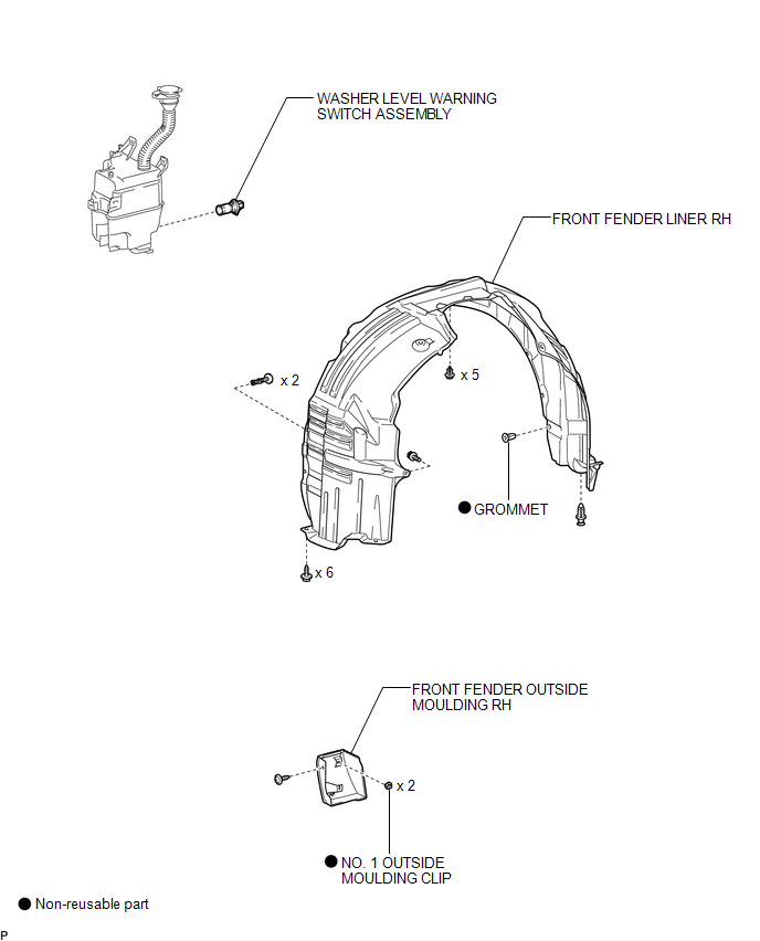
COMPONENTS
ILLUSTRATION
Inspection
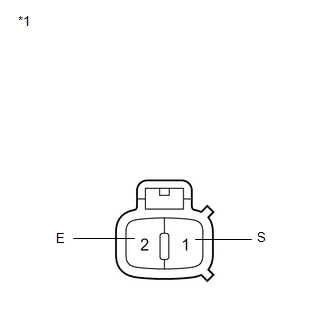
INSPECTION
PROCEDURE
1. INSPECT LEVEL WARNING SWITCH ASSEMBLY
HINT:
The following check should be performed with the windshield washer motor and pump installed to the washer jar.
(a) Fill the washer jar with washer fluid.
|
(b) Measure the resistance according to the value(s) in the table below. Standard Resistance:
If the result is not as specified, replace the level warning switch assembly. Text in Illustration
|
|
Removal
REMOVAL
PROCEDURE
1. REMOVE FRONT WHEEL RH
2. REMOVE FRONT FENDER OUTSIDE MOULDING RH
HINT:
Use the same procedure for the RH side and LH side (See page
.gif) ).
).
3. REMOVE FRONT FENDER LINER RH
4. DRAIN WINDSHIELD WASHER FLUID
5. REMOVE WASHER LEVEL WARNING SWITCH ASSEMBLY
|
(a) Disconnect the connector. |
|
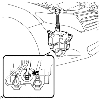
(b) Remove the washer level warning switch assembly.
Installation
INSTALLATION
PROCEDURE
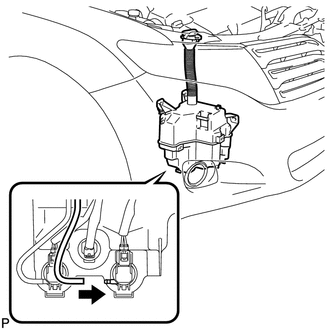
1. INSTALL WASHER LEVEL WARNING SWITCH ASSEMBLY
|
(a) Install the washer level warning switch assembly. |
|
.png)
(b) Connect the connector.
|
(c) Connect the washer hose. |
|
2. FILL WASHER JAR WITH WASHER FLUID
.gif)
3. INSTALL FRONT FENDER LINER RH
4. INSTALL FRONT FENDER OUTSIDE MOULDING RH
HINT:
Use the same procedure for the RH side and LH side (See page
).
5. INSTALL FRONT WHEEL RH
 Rear Wiper Rubber
Components
COMPONENTS
ILLUSTRATION
Replacement
REPLACEMENT
PROCEDURE
1. REMOVE REAR WIPER BLADE
(a) Disconnect the rear wiper arm head cap.
...
 Washer Motor(for Front Side)
Components
COMPONENTS
ILLUSTRATION
Removal
REMOVAL
PROCEDURE
1. REMOVE FRONT WHEEL RH
2. REMOVE FRONT FENDER OUTSIDE MOULDING RH
HINT:
Use the same procedure for the RH side and LH side ...
Other materials about Toyota Venza:
Initialization
INITIALIZATION
1. RESET TRANSAXLE COMPENSATION CODE
NOTICE:
If the following parts have been replaced, initialize the TCM and perform
the following "Reset Memory" and "Perform Road Test to Allow TCM to learn"
steps.
- ...
Installation
INSTALLATION
CAUTION / NOTICE / HINT
HINT:
Use the same procedure for the RH side and LH side.
The procedure listed below is for the LH side.
PROCEDURE
1. INSTALL FRONT POWER WINDOW REGULATOR MOTOR ASSEMBLY
NOTICE:
The regulator arm mu ...
Installation
INSTALLATION
PROCEDURE
1. INSTALL NO. 1 FUEL TANK CUSHION
(a) Install 8 new No. 1 fuel tank cushions to the fuel tank.
2. INSTALL FUEL MAIN TUBE SUPPORT
(a) Install the fuel main tube su ...

0.1419