Toyota Venza: Radio Antenna
Components
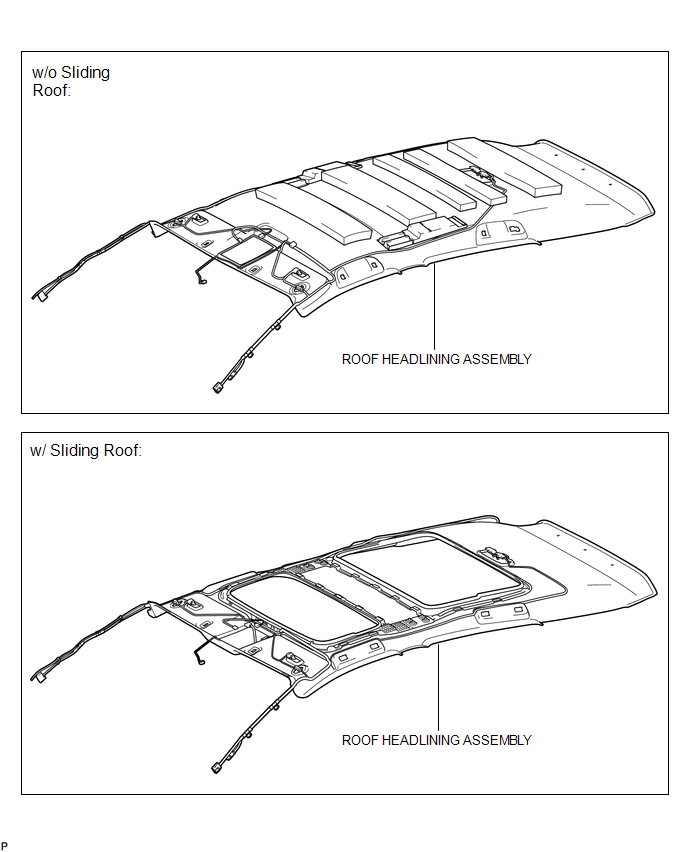
COMPONENTS
ILLUSTRATION
ILLUSTRATION
Installation
INSTALLATION
PROCEDURE
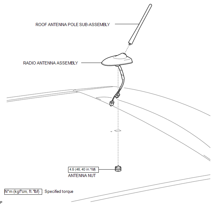
1. INSTALL RADIO ANTENNA ASSEMBLY
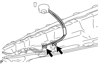
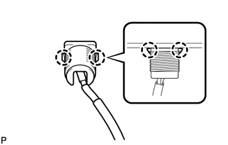
(a) Engage the 2 claws to install the radio antenna assembly.
|
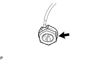
(b) Place the antenna cord in the cutout of the antenna nut. Text in Illustration
|
|

(c) Install the radio antenna assembly with the antenna nut.
Torque:
4.5 N·m {46 kgf·cm, 40 in·lbf}
(d) Connect the 2 connectors.
2. INSTALL ROOF ANTENNA POLE SUB-ASSEMBLY
3. INSTALL ROOF HEADLINING ASSEMBLY
(See page .gif) )
)
Removal
REMOVAL
PROCEDURE
1. REMOVE ROOF HEADLINING ASSEMBLY
(See page .gif) )
)
2. REMOVE ROOF ANTENNA POLE SUB-ASSEMBLY
3. REMOVE RADIO ANTENNA ASSEMBLY
|
(a) Disconnect the 2 connectors. |
|
|
(b) Remove the antenna nut. |
|
|
(c) Disengage the 2 claws and remove the radio antenna assembly. |
|
 Microphone
Components
COMPONENTS
ILLUSTRATION
Removal
REMOVAL
PROCEDURE
1. REMOVE INNER REAR VIEW MIRROR STAY HOLDER COVER
2. REMOVE TELEPHONE MICROPHONE ASSEMBLY (INNER REAR VIEW MIRROR ASSEMBLY ...

Other materials about Toyota Venza:
Transmission Fluid Temperature Sensor "A" Circuit Low Input (P0712,P0713)
DESCRIPTION
The Automatic Transmission Fluid (ATF) temperature sensor converts the fluid
temperature into a resistance value for use by the TCM.
The TCM applies a voltage to the temperature sensor through terminal THO1 of
the TCM.
The sensor resistanc ...
How To Proceed With Troubleshooting
CAUTION / NOTICE / HINT
HINT:
Use the following procedure to troubleshoot the lighting system.
*: Use the Techstream.
PROCEDURE
1.
VEHICLE BROUGHT TO WORKSHOP
NEXT
...
Rear Light Assembly
Components
COMPONENTS
ILLUSTRATION
On-vehicle Inspection
ON-VEHICLE INSPECTION
PROCEDURE
1. INSPECT REAR LIGHT ASSEMBLY
(a) Disconnect the connector from the rear light assembly.
(b) Measu ...

0.1226