Toyota Venza: Personal Light
Components
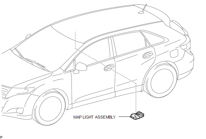
COMPONENTS
ILLUSTRATION
Removal
REMOVAL
PROCEDURE
1. REMOVE MAP LIGHT ASSEMBLY
|
(a) Using a moulding remover, disengage the 2 claws and 2 clips. Text in Illustration
|
|
.png)
(b) Disengage the fastener.
(c) Disconnect each connector and remove the map light assembly.
Installation
INSTALLATION
PROCEDURE
1. INSTALL MAP LIGHT ASSEMBLY
(a) Connect each connector.
|
(b) Engage the fastener. Text in Illustration
|
|
.png)
(c) Engage the 2 claws and 2 clips, and install the map light assembly.
 Luggage Compartment Room Light
Components
COMPONENTS
ILLUSTRATION
Removal
REMOVAL
PROCEDURE
1. REMOVE NO. 2 ROOM LIGHT ASSEMBLY
(a) Using a moulding remover, disengage the claw.
...

Other materials about Toyota Venza:
Removal
REMOVAL
PROCEDURE
1. REMOVE FRONT WHEELS
2. REMOVE FRONT STABILIZER LINK ASSEMBLY LH
(a) Remove the 2 nuts and front stabilizer link assembly LH.
HINT:
If the ball joint turns together with the nut, use a hexagon wrench (6
mm) to hold ...
Terminals Of Ecu
TERMINALS OF ECU
1. CHECK ENGINE SWITCH
(a) Disconnect the D13 engine switch connector.
(b) Measure the resistance according to the value(s) in the table below.
HINT:
Measure the values on the wire harness side with connector disconnected.
T ...
Short in Curtain Shield Squib RH Circuit (B1830/57-B1833/57)
DESCRIPTION
The curtain shield squib RH circuit consists of the center airbag sensor assembly
and curtain shield airbag assembly RH.
The center airbag sensor assembly uses this circuit to deploy the airbag when
deployment conditions are met.
These DTCs ...

0.1318